Installing the kpa3 amplifier module, Installing the fan panel – Elecraft KPA3 Manual User Manual
Page 16
16
Installing the KPA3 Amplifier Module
Your KPA3 module may produce a rattling sound when shaken. This is normal. It is
caused by ferrite beads sliding along wire leads in the module.
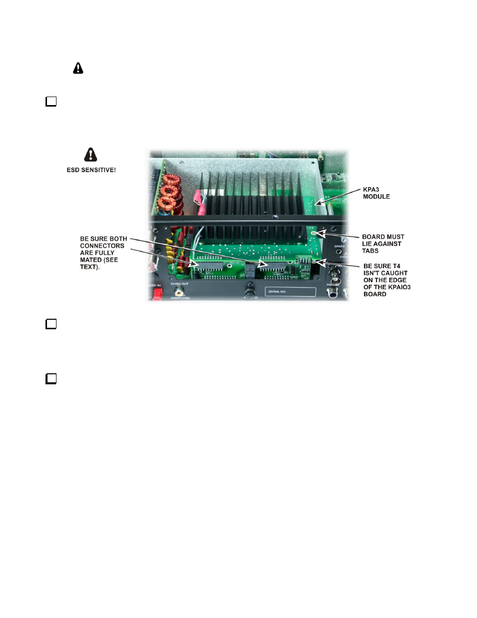
Place the KPA3 module inside the shield from the top. Mate the two connectors fully with the KPAIO3
board as shown in Figure 15. Like the KPAIO3 to RF board connectors, these connectors may require some
force to mate them fully. Do not place undue pressure on the RF board without supporting it. Recommend you
place your fingers on the bottom of the RF board, under the connectors to the KPAIO3 board, and squeeze down
with your thumbs on the KPA3 board above the connectors until they are fully mated.
Figure 15. Mounting the KPA3 Module.
Secure the KPA3 module to the rear shield tabs with three 4-40, 1/4” (6.4mm) zinc pan head screws. Place
a #4 inside tooth lock washer under each screw head.
Installing the Fan Panel
Current KPA3 fan panels have a hole near the circuit breaker marked ANT3 for the antenna connection to
the optional K144XV 2-meter module:
If you are adding the KPA3 to a K3 that has the K144XV option installed, install the connector and
cable you removed from the blank panel earlier in the ANT3 hole in the fan panel. Route the antenna
cable along the top of the KPA3 pc board across the opening for the fans and through the opening in the
shield near the KIO3 board.
If you do not have the K144XV option, a plastic plug is provided to fill this hole. Use the plug you
removed from the hole marked ANT3 in t he existing blank panel if you are updating a built K3. If you
are installing the KPA3 while building your K3 kit, the plug will be in the K3 Miscellaneous Bag.