Corners, Ii door fr, Corner identification and assembly – EFCO 945 Series User Manual
Page 23: Fig. 19
S
S
S
S
S
S
STC8
STC8
W160
STK8
STC8
8334
8331
8332
9297
8334
8342
8333
SECTION VI - CORNERS
CORNER IDENTIFICATION AND ASSEMBLY
DPS 04/2001
WC12
W160
STK8
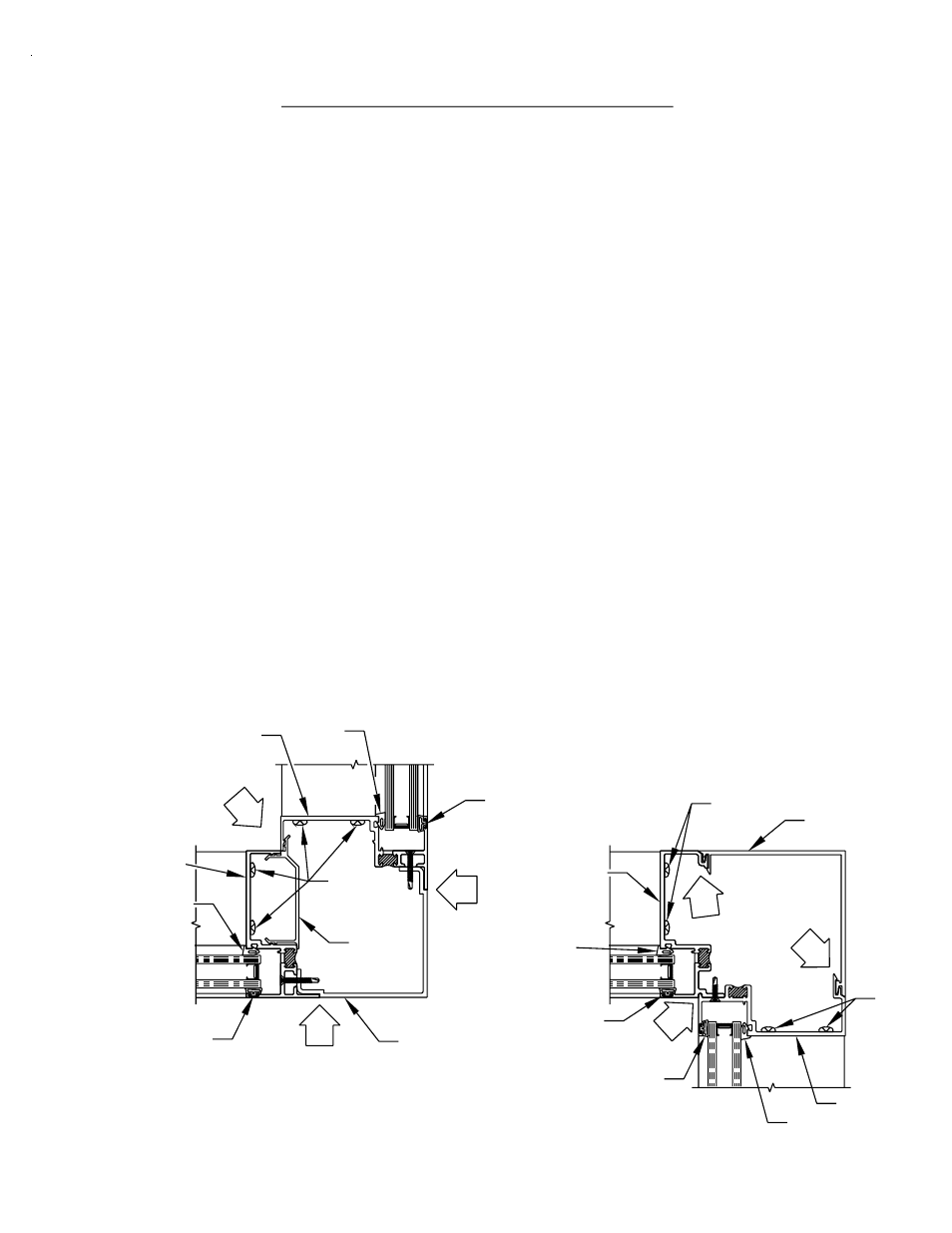
[FIG. 19]
WC12
W160
Proper identification of the required corner members is necessary to ensure a timely
installation process.
1) 90˚ captured outside corner
2) 90˚ captured inside corner
3) 90˚ S.S.G. inside corner
4) 90˚ S.S.G. outside corner
5) 135˚ S.S.G. outside corner
Determine that the subsill has been installed according to the instructions listed on Pages 13
through 20. Assemble the appropriate extrusions to create the required corner member.
Utilize the fasteners shown in Figures 19 through 21A on Pages 21 and 22. The fasteners
should be installed 6" from each end and 12" on center. Install the appropriate assembled
corner member into the subsill. It may be necessary to temporarily brace the vertical corner
member until the adjacent ladders are installed and anchored.
If door openings are required on a run that incorporates a corner member, begin at the door
frame and assemble towards the corner area with the required ladders. Unassembled
corner extrusions must be attached to the ladders, and the corner member must be
assembled after installation of both adjacent ladders.
STK4
W160
WC12
WC12
PAGE 21