EFCO S5600 Inside Glazed User Manual
Page 22
EFCO CORPORATION 6/2012 PART NO. Y304
Page 22 of 29
Series 5600 Inside Glazed Installation Instructions
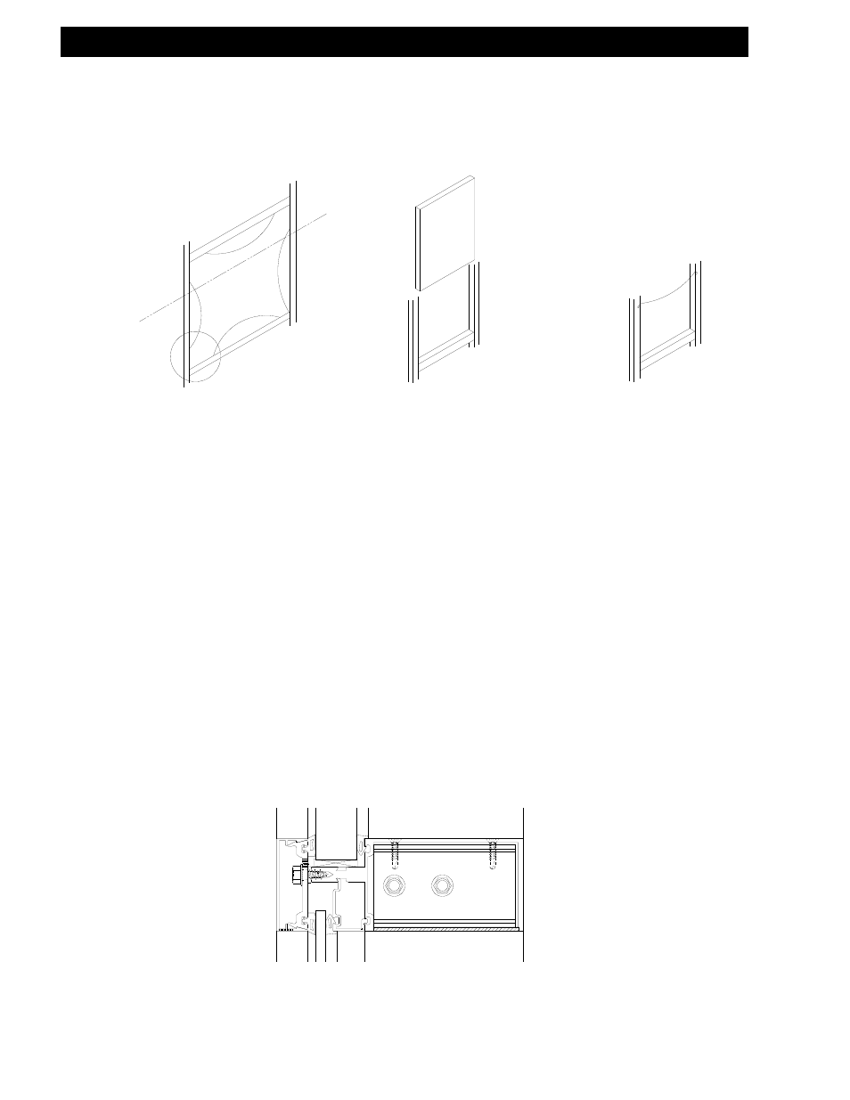
Section X: Glazing Installation
FIG. D
FIG. A
FIG. C
Stool Horizontal
Floor line
Ceiling horizontal
Molded corners
Drop-in Glazing
Infill
Tape top of
gasket assembly
to mullion face
when using
molded corners
Step #9 Glazing the Spandrel Areas at Floor Lines
A.) The top of each spandrel glass should consist of a horizontal assembly with bolt-on
pressure plate as shown in FIG. “D” below.
B.) Leave the horizontal above the floor line off (stool horizontal) while erecting frames.
C.) Set the exterior preset gasket in two sides and the sill of the opening for the spandrel
glass. Tape the top of the gasket on the mullion face. See FIG. “C” above.
D.) From the floor line, drop infill down into the glazing pocket, onto pre-located setting
blocks and into final position as shown in FIG. “B” above.
E.) Drop the sill horizontal down over the top of the glass and onto pre-attached shear
blocks.
*If molded corner gaskets are used, the exterior preset gasket must be installed
into the horizontal pressure plate prior to dropping it over the glass. Do not fully
tighten the pressure plate screws until after the horizontal is in final position. This
will allow for easy slip-on and alignment.
F.) Attach the horizontal to the shear block and torque the pressure plate screws as
required. Seal the horizontal and pressure plate as shown on page 9 - 10. Install the
horizontal face cap.
Notch bottom of horizontal
for drop-on application
Spandrel