Er configuration – Detex V40 ER User Manual
Page 8
103104 Page 8
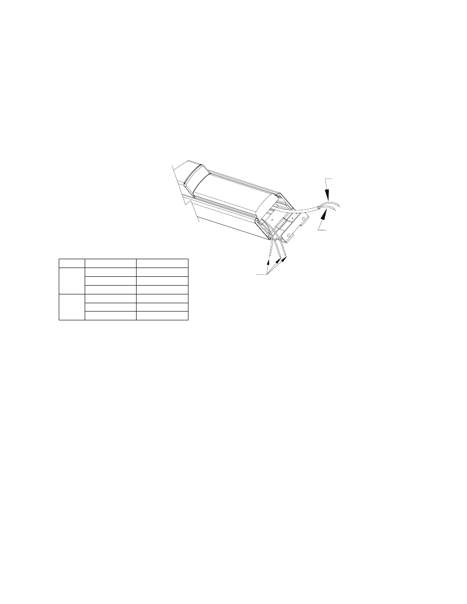
CONNECTIONS FOR THE ER MODEL
The red and black wires should be connected to the power supply control board (81-800, 82-800, or 83-800,
depending on the door configuration). See power supply instructions 101339 or 101340 as appropriate for typical
connections.
RETRACTING THE LATCH
The ER device must be connected to a Detex power supply/controller, 81-800, 82-800 or 83-800. With all the
connections made according to the power supply instructions, closing the contact will retract the latch. The
pushpad will be pulled down as the latch and deadbolt are retracted. The latch is held by an internal dogging
assembly until the contact is released/opened.
HOLDING THE LATCH RETRACTED
ER model holds the latch retracted as long as the control switch is maintained(closed).
RELEASING THE LATCH
ER is an electronically dogged latch. Opening the control switch (or contacts) causes the latching mechanism to
release. If an 8X-800 series Detex power supply is used, there is a slight delay from the opening of the switch
contacts to the release of the latch. This delay is intended for external signaling and is described in the power
supply instructions.
DETEX ER UNITS REQUIRE A DETEX POWER
SUPPLY/CONTROLLER; DETEX P/N 81-800-X, 82-800-X, OR 83-800-X
SEE POWER SUPPLY INSTALLATION INSTRUCTIONS(PACKAGED
WITH POWER SUPPLY) FOR COMPLETE INSTALLATION
PROCEDURE.
SENSITIVE
NOTE: POLARITY
RED (+)
BLACK(-)
POWER CABLE FROM ER MODULE
(CONNECT TO POWER SUPPLY)
ER CONFIGURATION
WIRES FROM EX OR EXV SWITCH
Chart
See
(Optional)
Amperage
Wire Color
Switch Position
50mA
max.
3A
max.
Grey
Brown
Yellow
Grey/Red
Brown/Red
Yellow/Red
Open
Common
Closed
Open
Common
Closed