3 rs-485 serial port connections, 4 power supply connections – Salter Brecknell WB-521 Series User Manual
Page 12
10
SBI521 Service Manual
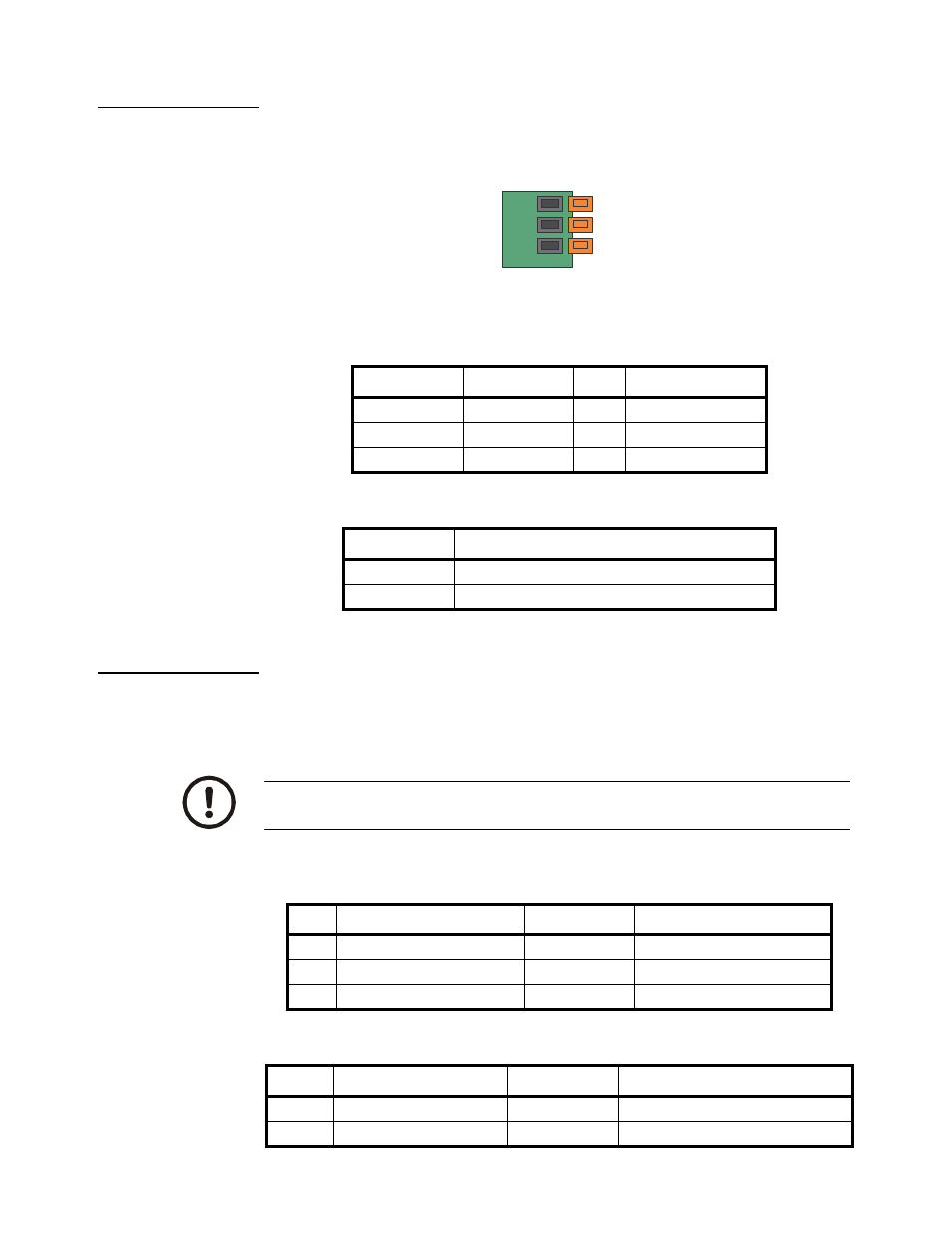
1.4.3 RS-485 Serial Port Connections
The SBI-521 indicator comes standard with one RS-485 network port designed for local
networks and multidrop communication links. Refer to
Table 1.10
and
Table 1.11
on
page 12
for COM2 jumpers.
Figure 1.5 RS-485 Connection
Table 1.4 RS-485 Port Connections
Table 1.5 Termination Resistor Jumper (JP4)
1.4.4 Power Supply Connections
The SBI-521 comes standard with an external AC to DC power adapter. Simply plug
the AC adapter into the indicator DC power jack and then plug into a standard wall
outlet.
Table 1.6 Adapter Power Input Connector (ADP)
Table 1.7 Battery Power Input Connector (BAT)
Designation
Description
Pin
Electrical Level
A
RS-485 signal A
1
0 - 5 VDC
B
RS-485 signal B
2
0 - 5 VDC
GND ground/common
3
0
VDC
Connected Pins
Function
1-2
RS485 terminal 120ohm resistor on board is disabled
2-3
RS485 terminal 120ohm resistor on board is enabled
1
GND
B
A
3
IMPORTANT: Make sure that the AC voltage appearing at the wall outlet
matches the input voltage marked on the AC adapter.
Pin
Definition
In/Out/Power
Electrical Level
1
Adapter input voltage +
Power input
12VDC (10.5-15VDC, ≥0.5A)
2
Adapter input voltage - (GND)
Power ground
0Vdc
3
Shell Earth
N/A
N/A
Pin
Definition
In/Out/Power
Electrical Level
1
Battery input voltage +
Power input
5.6-7.2Vdc (6V/2.8AH lead acid battery)
2
Battery input voltage -(GND)
Power ground
0Vdc