Model ii3.248210,113.248320, 113.248440 – Craftsman 113.248510 User Manual
Page 12
Attention! The text in this document has been recognized automatically. To view the original document, you can use the "Original mode".
MODEL II3.248210,113.248320,
113.248440
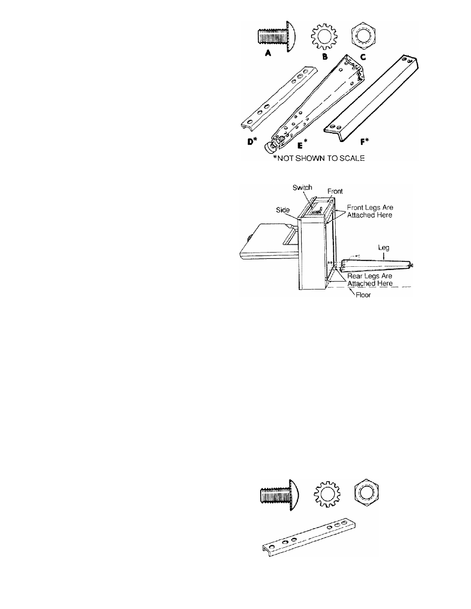
ATTACHING LEG SET
From the loose parts bag find the following hardware:
Item Description
Qty.
A
Truss Head Bolts Vi-20 x
’/2
................... 32
B
Lockwashers External V
a
........................32
C
Hex Nuts
1
/
4-20
....................................... 32
From the loose parts find the following items:
D
Leg Channel............................................. 1
E
Legs (with attached support brackets and
leveling feet)
4
F
Lower Stiffeners....................................... 4
1. Lay a piece of cardboard on the floor to keep from
scratching the saw.
2. Position the basic saw assembly on the floor as
shown below. The back cabinet of the saw should be
laying flat on the floor. It may be necessary to have
someone help you lift the saw.
3. Mount the two front legs to the basic saw assembly
using truss head bolts, lockwashers, and nuts.
Make sure that the four (4) holes in each corner of
the saw line up with the four (4) holes in the top of
each leg. At this timeonlyput bolts through thesWes
of the saw assembly nofthefront.Onlyfingertighten
nuts.
4. Position the leg channel inside the legset as shown.
Fasten the channel piece, leg, and saw together
with two (2) truss headbolts on each side. The
threaded section of the bolts should point towards
the inside of the basic saw assembly. Put a iock-
washerand hex nut on each bolt. Finger tighten nuts
at this time.
SAW
BASE
NUT
A
LOCKWASHER
I®: s
CHANNEL
LEG
_L_
TRUSS
HEAD
SCREW
Truss head screw, lockwasher, hex nut, and front channel piece.
12