Vermont castings, majestic products dvrtsb, Eb-1 electrical box, Alternate switch location – Vermont Casting DVRTSB User Manual
Page 8: Remote on/off switch installation
8
Vermont Castings, Majestic Products DVRTSB
10003848
The fireplace, when installed, must be
electrically connected and grounded in
accordance with local codes or, in the
absence of local codes, with the current
CSA C22.1 Canadian Electrical Code
For USA installations follow the local
codes and the national electrical code
ANSI/NFPA No. 70.
It is strongly suggested that the wiring of
the EB-1 Electrical Junction Box be
carried out by a licensed electrician.
Ensure that the power to the supply line
has been disconnected before commenc-
ing this procedure.
The EB-1 Electrical junction box has been supplied
standard on this model to allow for the easy connection
of an optional fan kit. (Fig. )
To connect the EB-1 box to the house electrical supply
follow the steps below.
1. Remove the front cover of the EB-1 box.
2. Remove the plug socket assembly from the EB-1
box.
3. Feed the supply line in from the outside through the
electrical knock-out.
4. Connect the ground wire of the supply line to the
green screw of the socket assembly.
5. Connect the white wire of the power line to the
chrome screw of the socket assembly.
6. Connect the black wire of the power supply line to
the brass screw (polarized) of the socket assembly.
7. Refit the socket assembly back into the electrical
box and replace the cover plate.
8. The EB-1 electrical junction box is now ready to
supply power to the FK12 or FK24 fan kits, if fitted.
EB-1 Electrical Box
1. Thread the wiring through the holes on the end
panels of the appliance. Take care not to cut the
wire or insulation on metal edges. Route the wire to
a conveniently located receptacle box.
2. Attach the wire to the ON/OFF switch and install the
switch into the receptacle box.
3. Connect the other ends of the wire to the gas
control valve. (Fig. 7)
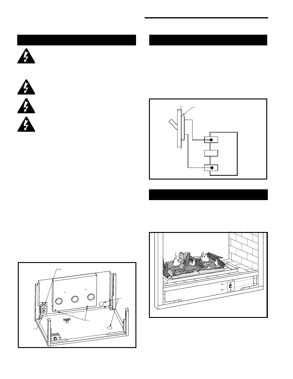
Alternate Switch Location
The remote switch can be installed on the front/side of
the access door. Simply mount the switch to the
bracket provided and screw the bracket to either side of
the frame, lining up the screws with the pre-punched
holes. (Fig. 8)
Remote ON/OFF Switch Installation
Electrical Box (EB-1)
FK24 Fan
Kit
Mounting
Studs
Retaining
Screw
1
¹⁄₂
”
Gas
Inlet
Holes
FP1375
Fig. 6 EB-1 electrical box.
TP
TH
TP
TH
Remote ON/OFF Switch or
Thermostat or Remote Control
Gas
Control
Valve
FP1376
Fig. 7 Remote switch wiring diagram.
FP1377
Fig. 8 Alternate switch location.