Vermont castings, majestic products dvrtsb, Fuel conversion instructions – Vermont Casting DVRTSB User Manual
Page 28
28
Vermont Castings, Majestic Products DVRTSB
10003848
Fuel Conversion Instructions
The conversion of this appliance from
one gas to another must be carried out
by a qualified service technician.
1. Disconnect power to unit and shut off the gas
supply.
2. Remove the glass (Refer to “Glass Removal”
Section.)
3. Carefully remove the logs & lava rock material.
4. Remove the screws that are holding the burner
housing in place.
5. Remove the burner housing. On this model you may
need to loosen the pilot bracket retaining screw/nut
and tilt pilot and bracket assembly to gain sufficient
clearance to remove the burner housing.
6. Remove front and rear orifice and replace with
orifice supplied in the conversion kit.
7. SIT top Convertible Pilot
Gently lift off pilot hood from the pilot. (Do not
remove the spring clip holding the hood in place).
Using a size 5/32” Allen key unscrew the exposed
orifice. Insert the new orifice supplied in the kit, do
not over tighten the orifice. Replace the pilot hood
ensuring the index tab aligns with the notch on the
hood.
PSE Pilot
Using a suitable wrench on hexagonal body un-
screw the pilot hood assembly from the pilot, do not
twist the hood itself. Remove the orifice and replace
it with the new orifice supplied in the kit. Refit the
pilot hood assembly. Do not over-tighten the pilot
hood. The hood must return to its original align-
ment. Take care not to damage the thermocouple,
thermopile or igniter.
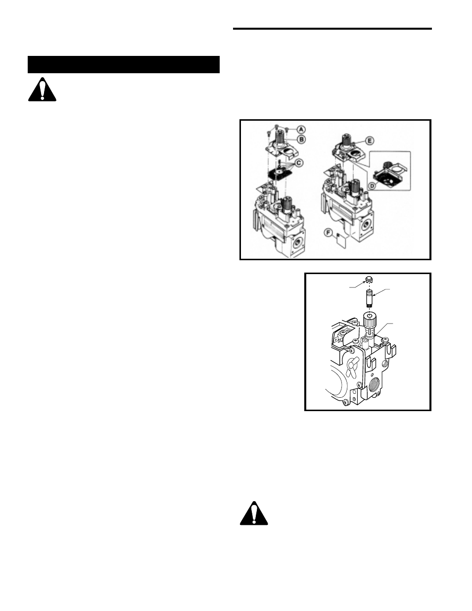
8. SIT 820 NOVA Gas Control Valve (Fig. 11)
a) Using a Torx T20 or slotted screwdriver, remove
and save three pressure regulator mounting screws
(A), pressure regulator tower (B) and diaphram (C).
b) Ensure the rubber gasket (D) is properly posi-
tioned and install the new HI/LO pressure regulator
to valve using the new screws (E) supplied with the
kit. Tighten screws securely. (Reference torque - 25
in.LB)
c) Install the enclosed identification label (F) to the
valve body where it can be easily seen.
Honeywell Gas Control Valve (Fig. 12)
The Honeywell valve fitted to this unit is suitable for
use with LP or Natural Gas. It is converted to
required gas application by the installation of a color
coded “conversion screw”.
a. Using a suitable small screw-driver lift out the
central regulator cap from the “HI/LO” knob on the
valve.
b. Unscrew the exposed conversion screw.
c. Insert the new color coded conversion screw. Do
not over-tighten the screw, it must be fingertight.
d. Refit the regulator cap.
e. Mount
conversion
label sup-
plied with
conversion
screw to
valve in a
visible
position.
9. Reassemble
fireplace in
the reverse
order,
except for
front glass.
Leave this
off until after unit has been checked for leaks and
the gas supply has been bled.
10. After bleeding gas line and checking for leaks with
a soap solution, replace the front glass. Fire up the
unit, check for flame impingment on logs, adjusting
them if necessary. Check manifold and supply
pressures. Make sure screws are tightened after
checking pressure.
The procedure for converting from one
gas to another is the same regardless of
the initial gas used. The only variation is
in the orifice sizes and component part
numbers. Your authorized service pro-
vider will ensure correct parts are used.
Fig. 5 NOVA SIT820 gas valve.
820
L
OH
I
Regulator Cap
Conversion
Screw
Pressure
Regulator
Housing
HV102
Fig. 46 Honeywell gas valve.