Vermont castings, majestic products dvrtsb, Vertical sidewall applications, Rear wall vent installation – Vermont Casting DVRTSB User Manual
Page 14
14
Vermont Castings, Majestic Products DVRTSB
10003848
STEP 3
Measure the horizontal length requirement for the
venting including a 2” (50mm) overlap, i.e. from the
elbow to the outside wall face plus 2” (50mm) (or the
distance required if installing a second 90
°
elbow. (Fig.
17)
STEP 4
Install the 4” (100mm) vent to the appliance collar and
secure with three (3) sheetmetal screws. Install the 7”
(175mm) vent pipe to the appliance collar and secure
with three (3) sheet metal screws. It is not necessary to
seal this connection.
It is critical that there is no downward
slope away from the appliance when
connecting the vent or elbow.
STEP 5
Guide the vent through the vent hole as you place the
appliance in its installed position. Guide the 4”
(100mm) and 7” (175mm) collars of the vent termina-
tion into the outer ends of the venting. Do not force the
termination. If the vent pipes do not align with the
temination remove and realign the venting at the
appliance flue collars. Attach the termination to the wall
as outlined in the instruction sheet supplied with the
termination.
Vertical Sidewall Applications
20"
(508 mm)
FP1379
Fig. 16 Rear vent application, no elbows.
Rear Wall Vent Installation
STEP 1
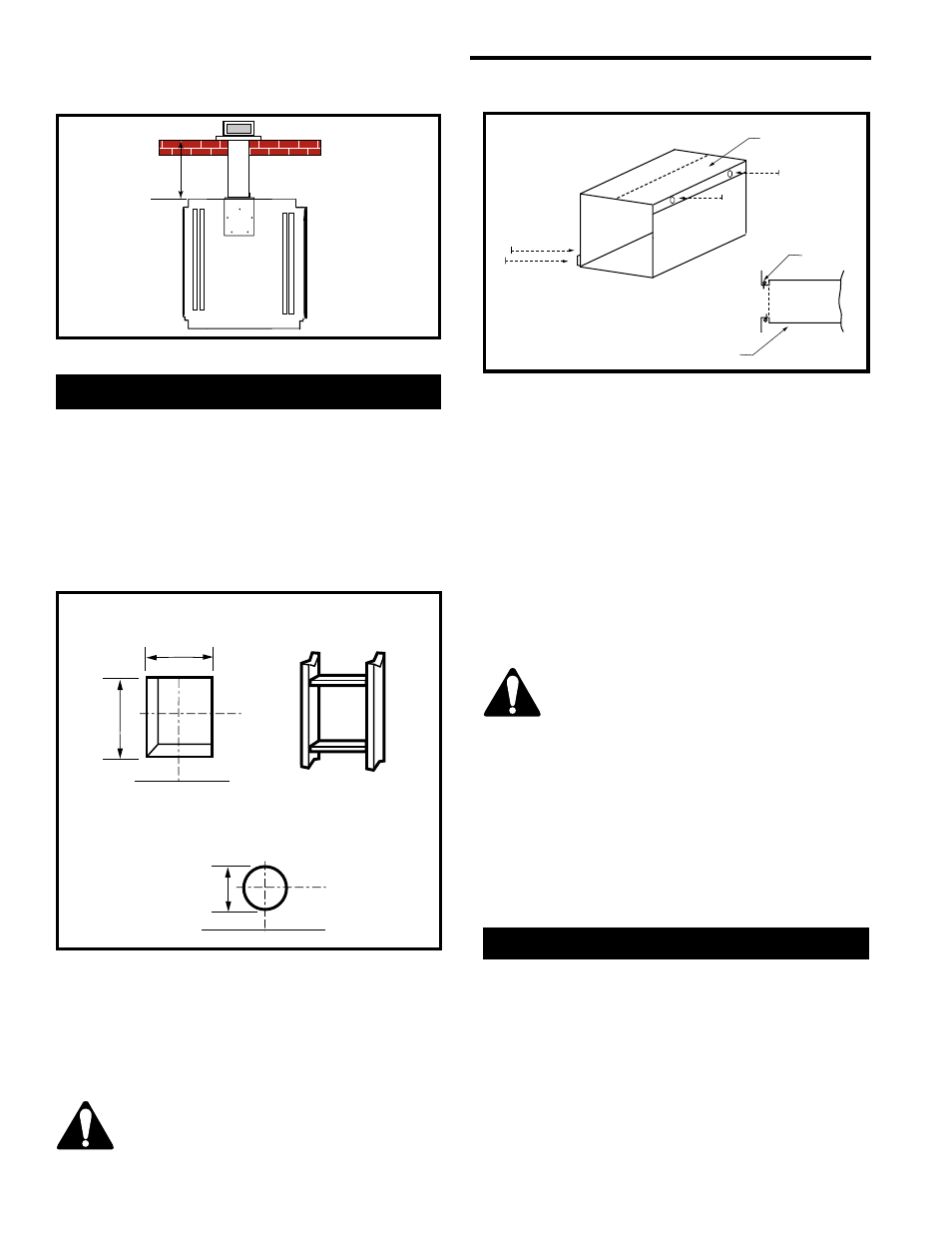
Locate and cut the vent opening in the wall. (Fig. 17)
For combustible walls first frame in opening. ( Fig. 17)
Combustible Walls: Cut a 10
³⁄₈
”H x 9
³⁄₈
” W (265 x
240mm) hole through the exterior wall and frame.
(Fig.21)
Noncombustible Walls: Hole opening must be 7
¹⁄₂
”
(190 mm) in diameter.
Vent Opening for Combustible Wall
9
³⁄₈
”
(240mm)
10
³⁄₈
”
(265mm)
Framing Detail
Opening for Noncombustible Wall
7
¹⁄₂
”
(190mm)
VO584-100
Fig. 17 Locate vent opening on wall.
STEP 2
Measure wall thickness and cut zero clearance sleeve
parts to proper length (MAXIMUM 12”/305mm). As-
semble sleeve to its maximum opening (10
³⁄₈
” x 9
³⁄₈
”)
and attach to firestop with #8 sheet metal screws
(supplied). Install firestop assembly. (Fig. 18)
Zero clearance sleeve is only required
for combustible walls.
Max. Length 12”
(305mm)
#8 Screws (2)
#8 Screws
(2)
Adjustable Zero Clearance Sleeve
ZCS101
#8 Screws (2)
Firestop
Adjustable Zero
Clearance Sleeve
Fig. 18 Adjustable zero clearance sleeve.
Since it is very important the venting system maintain
its balance between the combustion air intake and the
flue gas exhaust, certain limitations as to vent configu-
rations apply and must be strictly adhered to.
The vent graph showing the relationship between
vertical and horizontal side wall venting will help to
determine the various dimensions allowable.