Vermont castings, majestic products dvrtsb – Vermont Casting DVRTSB User Manual
Page 18
18
Vermont Castings, Majestic Products DVRTSB
10003848
1. Locate your fireplace.
2. Plumb to center of the (4”) flue collar from ceiling
above and mark position.
3. Cut opening equal to 9
³⁄₈
” x 9
³⁄₈
” (240 x 240mm).
4. Proceed to plumb for additional openings through
the roof. In all cases, the opening must provide a
minimum of 1” (25mm) clearance to the vent pipe,
i.e., the hole must be at least 9
³⁄₈
” x 9
³⁄₈
” (240 x
240mm).
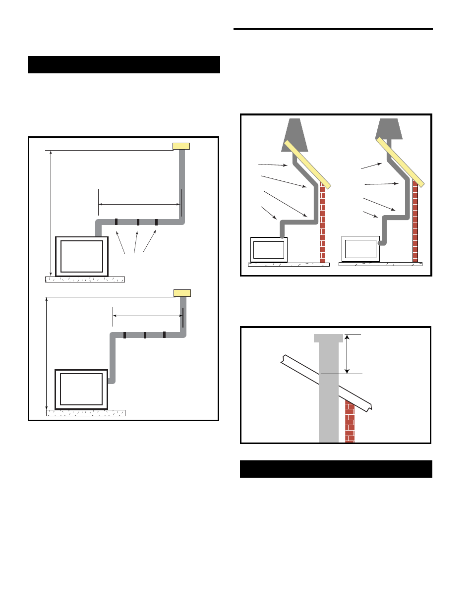
This Gas Fireplace has been approved for:
•
Vertical installations up to 40’ (12m) in height. Up to
a 10’ (3m) horizontal vent run can be installed within
the vent system using a maximum of two 90
°
elbows. (Fig. 29 & 30)
Vertical Through-the-Roof Applications
•
Up to two (2) 45
°
elbows may be used within the
horizontal run. For each 45
°
elbow used on the
horizontal level the maximum horizontal length must
be reduced by 18” (457mm).
Example: Maximum horizontal length
0 x 45
°
elbows = 10’ (3m)
1 x 45
°
elbows = 8.5’ (2.6m)
2 x 45
°
elbows = 7’ (2.1m)
•
A minimum of an 8’ (2.4m) vertical rise.
•
A maximum of two (2) sets of 45
°
elbow offsets can
be used within these vertical installation. From 0 to a
maximum of 8’ of vent pipe can be used between
elbows. (Fig. 30)
•
7DVCS supports offsets. (Fig. 32) This application
will require that you first determine the roof pitch and
use the appropriate starter kit. (See Venting
Components List)
•
The maximum angular variation allowed in the
system is 270˚. (Fig. 30)
Vertical Through-The-Roof Installation
•
The minimum height of the vent above the highest
point of penetration through the foof is 24” (610mm)
(Fig. 31)
Max. 10’ (3m)
Max. Height 40’ (12.2m)
Min. Height 8’ (2.4m)
Max.
Height 40’ (12.2m)
Min.
Height 8’ (2.4 m)
Max. 10’ (3m)
Support straps
every 36" (914mm)
FP1387
Fig. 29 Support for horizontal runs.
1
2
3
4
1
2
3
4
1 + 2 + 3 + 4 = 270
o
FP1389
Fig. 30 Maximum elbow usage.
Min.
2’ (610 mm)
FP1389
Fig. 31 Minimum termination to roof clearance.