Vermont castings, majestic products dvrtsb, Framing and finishing hearth mantels, Clearance to combustibles final finishing – Vermont Casting DVRTSB User Manual
Page 6: Mantel chart
6
Vermont Castings, Majestic Products DVRTSB
10003848
Appliance
Top ................................................... (0”) 0mm to stand-off
Bottom ................................................................. (0”) 0mm
Back ........................................ (1/2”) 13 mm to rear panel
Side Wall ............................................................ (0”) 0mm.
(behind side glass panel)
Venting
Concentric sections of DV Vent
Top, bottom & sides ........................................... (1”) 25mm
Non-concentric sections of DV Vent
Side and bottom ................................................ (1”) 25mm
Top ..................................................................... (2”) 50mm
1. Choose the unit location.
2. Place the unit into position and secure it to the floor
with 1
¹⁄₂
” (38mm) screws, or nails. The holes to
secure the unit to the floor are located just behind
the access door grille on the left and right side of the
unit.
3. Frame in the fireplace with a header across the top.
It is important to allow for the finished wall face when
setting the depth of the frame.
4. Drywall (sheetrock) or wood material may be placed
with a zero clearance to the top edges of the appli-
ance when finishing walls above sides of the appli-
ance with glass windows. Attach the wall finishing to
the constructed frame not the appliance.
5. On DVRTSB models, drywall, wood or wood
molding may be placed with zero clearance to the
rear wall of the unit, along the vertical edge formed
by the standoffs to intersection of the rear wall to the
side wall containing the small glass window. Attach
the wall finishing to the constructed frame, not the
appliance.
Cold climate installation recommendation:
When installing this unit against a non-
insulated exterior wall or chase, it is
mandatory that the outer walls be
insulated to conform to applicable
insulation codes.
Framing and Finishing
Hearth
Mantels
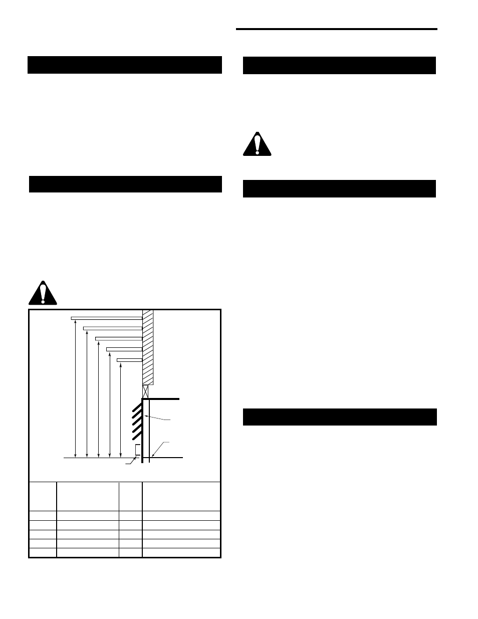
The height that a combustible mantel is fitted above
the fireplace is dependent on the depth of the mantel.
This also applies to the distance between the mantel
leg (if fitted) and the fireplace.
For the correct mounting height and widths refer to
Figure and the Mantel Chart below.
Noncombustible mantels and legs may be installed at
any height and width around the appliance.
When using paint or lacquer to finish the
mantel, such paint or lacquer must be
heat resistant to prevent discoloration.
Clearance to Combustibles
Final Finishing
Nonconbustible materials such as brick or tile may be
extended over the edges of the face of the appliance.
DO NOT cover any vent or grille panels.
Mantel Chart
Mantel Shelf
Mantel from Top
Ref.
or Breast Plate
Ref. of Comb. Chamber
Depth
V
10” (254mm)
A
19” (483mm)
W
8” (203mm)
B
17” (432mm)
X
6” (152mm)
C
15” (381mm)
Y
4” (101mm)
D
13” (330mm)
Z
2” (50mm)
E
11” (279mm)
A
B
C
D
E
V
W
X
Y
Z
Fireplace
CFM146
NOTE: The above mantel shelf chart will be
applied for the front and two sides of the fireplace.
Top Louvre
Assembly
Top of
Combustion
Chamber
Bottom of Door
Trim
Fig. 4 Combustible mantel minimum installation.
A hearth is not mandatory but is recommended for
aesthetic purposes. We recommend a noncombustible
hearth which projects out 12” (305mm) or more from
the front of the fireplace.