Vermont castings, majestic products dvrtsb, Below grade installations – Vermont Casting DVRTSB User Manual
Page 17
17
Vermont Castings, Majestic Products DVRTSB
10003848
X
X
FP1385
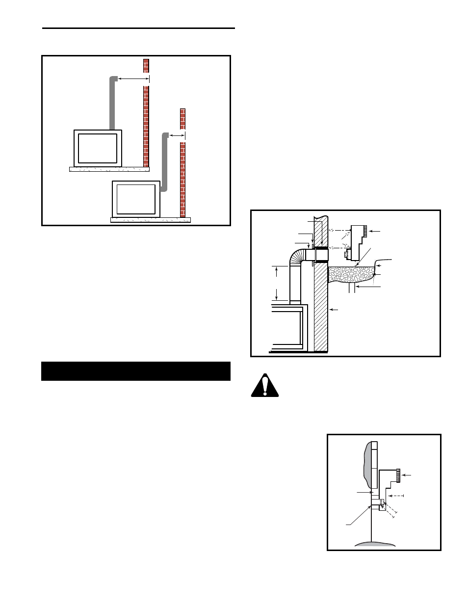
Fig. 26 Horizontal length requirement.
STEP 7
Apply high temperature sealant to 4” (100mm) and 7”
(175mm) collars or the termination one inch away from
crimped end. Guide the vent terminations 4” and 7”
collars into their respective vent pipes. Double check
that the vent pipes overlap the collars by 2” (50mm).
Secure the termination to the wall with screws provided
and caulk around the wall plate to weatherproof.
Support the horizontal pipes every 36” (914mm)
with metal pipe straps.
Check the fireplace to make sure that it is levelled
and properly positioned.
Below Grade Installations
When it is not possible to meet the required vent
terminal clearances of 12” (305mm) above grade level
a starter kit is recommended. It allows installation depth
of down to 7” (178mm) below grade level. The 7”
(178mm) is measured from the center of the horizontal
vent pipe as it penetrates through the wall.
If venting system is installed below ground, we recom-
mend a window well with adequate and proper drain-
age.
Ensure sidewall venting clearances are observed.
If installing a snorkel, a minimum 24” (610mm) vertical
rise is necessary. The maximum horizontal run with the
24” (610mm) vertical pipe is 36” (914mm). The meas-
urement is taken from the collar of the fireplace (or
transition elbow) to the face of the exterior wall. See
Vent Chart (see ‘How to use the Vent Graph’) for
extended horizontal runs if the vertical exceeds 24”
(610mm).
1. Establish vent hole through the wall. (Fig. 23)
2. Remove soil to a depth of approximately 16"
(406mm) below base of snorkel. Install drain pipe.
Install window well (not supplied). Refill hole with 12"
(305mm) of coarse gravel leaving a clearance of
approximately 4" (100mm) below snorkel. (Fig. 27)
3. Install vent system.
4. Ensure a watertight seal is made around the vent
pipe coming through the wall.
5. Apply high temperature sealant caulking (supplied)
around the 4” and 7” snorkel collars.
6. Slide the snorkel into the vent pipes and secure to
the wall.
7. Level the soil so as to maintain a 4” (100mm) clear-
ance below snorkel. (Fig. 27)
Zero Clearance
Sleeve if Required
Firestop
7” Pipe
7DVSKS
(Snorkel)
Screws
Minimum 4” Clearance
Ground
Window Well
Gravel
Drain
Foundation Wall
•
A minimum of 24” (610mm) vertical
pipe must be installed when using
the 7DVSKS/7TDVSKS kit.
•
The 22” vertical rise (center to
center) of the snorkel may be
included for calculation of max.
horizontal run.
24” (610mm)
Minimum
FP1386
Fig. 27 Below grade installation.
Do not back fill around snorkel.
A clearance of at least 4” (100mm) must
be maintained between the snorkel and
the soil.
If the foundation is recessed, use recess brackets (not
supplied) for
securing lower
portion of the
snorkel. Fasten
brackets to wall first,
then secure to
snorkel with self
drilling #8 x 1/2
sheetmetal screws.
It will be necessary
to extend vent pipes
out as far as
protruding wall face.
(Fig. 28)
Snorkel
Wall
Screws
Sheet Metal
Screws
Watertight
Seal
Around
Pipe
Foundation
Recess
CFM139
Fig. 28 Snorkel installatin, recessed
foundation.