Installation instructions – Qmark MUH35 - Unit Heater User Manual
Page 2
INSTALLATION
INSTRUCTIONS
General
Location of Heater
This heater has user controls. It may be desirable to reach
these controls after installation.
The direction of air flow should not be restricted by columns,
machinery, etc., and the air flow should wipe exposed walls
rather than blowing directly at them. When more than one
heater is used in an area, the heaters should be arranged so
that the air discharge of each heater supports the air flow of the
others to provide best circulation of warm air.
Ceiling Mount
This heater may be mounted to any ceiling that will support the
weight of the heater. See Figure 2.
1. Remove the mounting stand from the heater, then remove
four rubber grommets from stand.
2. Secure stand to structural members of ceiling with four 1/4”
diameter bolts (not provided). In wood joist use 1-1/2” long
lag bolts. In steel beams use machine bolts secured with
nuts and lockwashers. Never use bolts smaller than 1/4”
diameter.
3. Replace the heater in the stand and tighten knobs to lock in
place. Two large rubberwashers go between heater and
stand, one on either side.
Wall Mount
This heater may be mounted on any wall that will support the
weight of the heater. See Figure 3.
1. Remove the mounting stand from the heater, then remove
four rubber grommets from stand.
2. Secure stand to structural members of wall with four 1/4” dia.
X 1-1/2” long lag bolts (not provided). In masonry walls use
metal expansion shields or toggle bolts. Never use bolts
smaller than 1/4” diameter.
3. Replace the heater in the stand and tighten knobs to lock in
place. Two large rubber washers go between heater and
stand, one on either side.
To prevent a possible fire, injury to persons or damage to the
heater, adhere to the following:
1.
Disconnect all power coming to heater at main service
panel before wiring or servicing.
2. All wiring procedures and connections must be in accor-
dance with the National and Local Codes having jurisdic-
tion and the heater must be grounded.
3. Verify the power supply voltage coming to heater matches
the ratings as shown on the heater nameplate.
CAUTION: ENERGIZING HEATER AT A VOLTAGE GREATER
THAN THE VOLTAGE PRINTED ON THE NAMEPLATE WILL
DAMAGE THE HEATER AND VOID THE WARRANTY AND
COULD CAUSE A FIRE.
4. CAUTION - High temperature, risk of fire, keep electrical
cords, drapery, furnishings, and other combustibles at least
3 feet (0.9 m) from front of heater. Do not install heater
behind doors, below towel racks, or in an area where it is
subject to being blocked by furniture, curtains or storage
materials. Hot air from the heater may damage certain fab-
rics and plastics.
5. To reduce the risk of fire, do not store or use gasoline or
other flammable vapors and liquids in the vicinity of the
heater.
6. When heater is to be wall or ceiling mounted, the anchoring
provisions must be of sufficient strength to support the total
weight of the heater plus the weight of the mounting provi-
sions. Failure to properly secure the supporting members
of the building structure could allow the heater to fall.
7.
The following minimum clearances must be maintained:
Bottom of heater to floor - minimum 6’ (1829 mm) -
maximum height 15’ (4572 mm)
Sides of heater to adjacent wall - minimum 8” (203 mm)
When wall mounted, top of heater to ceiling 8” (203 mm)
When ceiling mounted, back of heater to wall 8”(203 mm)
Clearance in front of heater - 5’ (1524 mm)
8. Do not use this heater for dry out as the paint, plaster, saw-
dust and drywall sanding dust will permanently damage the
heater and must be kept out of the heater.
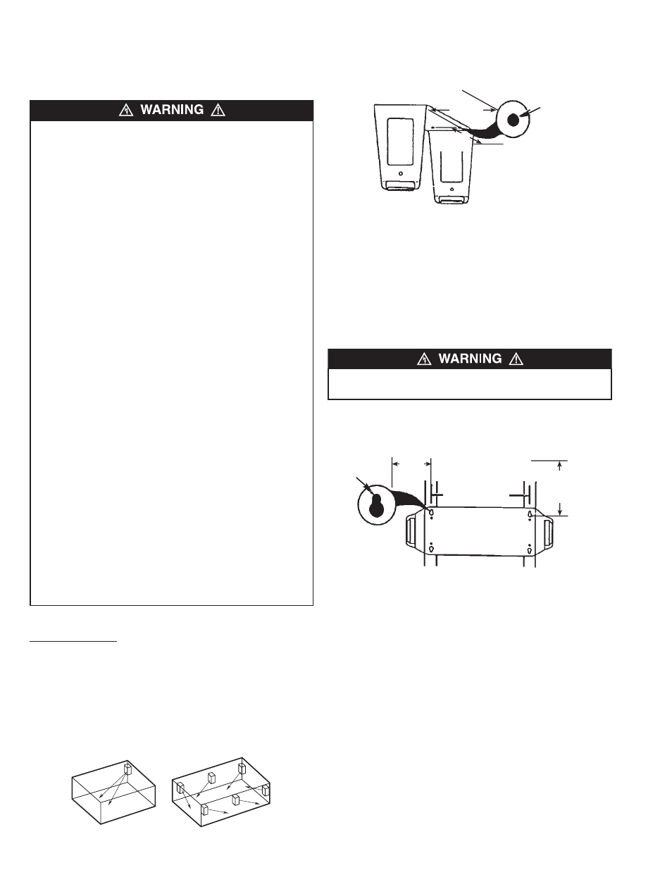
TO PREVENT HEATER FROM POSSIBLY FALLING, DO NOT
USE KEYHOLE SLOTS FOR CEILING MOUNT APPLICATION.
2
MIN. 8"
TO WALL
MIN. 8"
TO WALL
CIRCULAR
HOLE
USE CIRCULAR
HOLES FOR CEILING
MOUNTING. DO NOT
USE KEYHOLES.
Figure 1
Figure 2
MIN
8" TO
CEILING
TO WALL
MIN 8"
KEYHOLE
SLOT
MOUNTING
HOLES
ARE 16” O.C.
USE KEYHOLES
FOR WALL
MOUNTING
Figure 3