Caution – Qmark AWH4000 Series - Architectural Heavy-Duty Wall Heaters User Manual
Page 3
Note to Installer: Converting heater to half wattage
(Not applicable to WH3150 and WH3180, 120 Volt Models)
The WH Series wall heaters are manufactured and shipped at the higher
rated wattage. Full wattage heaters can be converted to half wattage by
doing the following steps.
1. Remove the red jumper wire as shown in Figure 3 and discard.
2. To permanently make the heater half wattage, cut the male terminal
spade, carefully not to damage the cold pin and discard.
3. Mark the wattage of the heater on the white label inside the backbox.
Installation of Back Box with Optional
Surface-Mounting Frame WHSM (See Figure 4)
1. Secure back box to wall with knockouts in upper right hand corner using
screws and anchors.
2. Hang the surface-mounting frame on the back box. Ensure that the back
edge of the surface-mounting frame is flush against the wall.
NOTE: If heater is located in a high traffic area, where it may be subject-
ed to vandalism or abuse, take extreme care to see that the box is firmly
attached to the wall.
3. Power Supply Wiring
NOTE: Wiring Compartment Volume - 119in
3
(1950cm
3
).
a. Run a power supply cable into the area to the right of the mounting
frame. Arrangement of wiring to this point must be in accordance
with National and Local codes.Refer to specifications on page 2 for
proper wire size.
NOTE: If the wiring is to run through the wall, cut a hole in the area of the top
of the back box. Run the supply wire through this hole. Then remove the
“knockout” from the top of the box and
proceed to step C.
b. Remove the “knockout” on the top side of the frame.
c. Remove disconnect switch bracket by loosening the two screws on
the right side.
d. Feed the power supply cable through the frame allowing 6" (152mm)
of lead to remain inside the back box (using cable clamp, connector,
or other suitable strain relief).
e. Secure the power supply cable to the back box (using cable clamp,
connector, or other suitable strain relief) allowing 6" (152mm) of lead
to remain inside the back box.
f. Connect supply wires to blue wires of disconnect switch using wiring
connectors (see wiring diagram, pg. 4).
g. Ground the back box by connecting the supply ground leadwire to
the green ground screw located in the inside top of the back box.
h. Secure disconnect switch bracket in place.
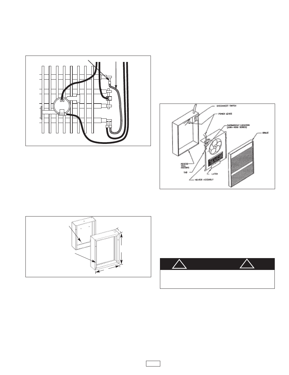
Installation of Heater Assembly and Grille
After back box is completely installed and no further construction dirt is expect-
ed, clean debris from back box and remove heater assembly from its carton.
Then refer to Figure 5 and proceed as follows:
1. Insert the heater assembly into back box, placing the four mounting holes
(with key-hole slots) over the screws in the box. Tighten all screws securely.
2. If surface-mounting frame is used, ensure that the frame is even with all four
heater assembly tabs before tightening screws.
3. Connect the two disconnected switch wires to the heat control switch (ther-
mostat) leads using wirenuts. After connection, push wires back into the
opening.
4. Turn thermostat to the extreme counterclockwise position.
5. Push disconnect switch into ON position.
6. Latch at bottom of heater assembly should be in up position.
7. Mount grille over tabs on fan deck and push down until grille is secure.
8. Insert screwdriver through bottom louver in grille and loosen screw while
holding bottom of grille against wall. This will allow latch to drop in place.
Tighten screw.
Operation
1. Rotate the thermostat fully clockwise. This should energize the heating
elements and cause warm air to flow from the hot air discharge at the
openings in the bottom of the grille.
2. After the operation check, rotate the thermostat to the desired position to
obtain room comfort.
NOTE: For best results, the heater should be left “ON”
constantly during the heating season because the thermostat, when properly
set, will maintain the desired temperature.
Cleaning & Maintenance
To maintain optimum performance and efficiency, heater should be cleaned
and checked periodically. It is recommended the heater be cleaned at least
annually. (more often if used in a dirty environment)
TO CLEAN HEATER:
1. Disconnect power to heater at main panel or breaker.
2. Remove thermostat knob (if provided) and remove front cover (grille)
as follows: (See figure 4)
–Insert screw driver through bottom louver and loosen one screw that
holds latch mechanism.
–Lift front cover upward and pull top outward to remove.
3. Push ON/OFF switch to OFF position.
4. Using vacuum cleaner knozzle, brush, or dust cloth, remove dust and
any foreign material from heater. Use care to not bend fan blade or
damage heater wiring. (Spin blade by hand to make sure it turns freely.)
5. Push ON/OFF switch to ON position.
6. Replace front cover and secure latch mechanism. (See installation of
Heater Assembly and Grille.)
7. Reconnect power to heater and verify that heater operates properly.
Male terminal spade
Red jumper wire
Fig. 4: Surface Mounting
Installation
MOUNT BACK BOX
TO WALL USING
REAR MOUNTING
HOLES.
HANG FRAME
ON BACK BOX.
15-5/32 "
(385mm)
19"
(482mm)
3-13/16"
(97mm)
Fig. 5
Fig. 3
3
CAUTION
TO PREVENT POSSIBLE ELECTRIC SHOCK, ALWAYS DISCON-
NECT ALL POWER TO HEATER AT MAIN DISCONNECT PANEL
OR FUSE BOX BEFORE CLEANING OR MAINTENANCE TO
HEATER.
!
!