Configuring drives, Connecting drive cables, Configuring drives -4 – Dell Dimension L___cx User Manual
Page 46: Connecting drive cables -4, Figure 3-3, Dc power cable connector -4
3-4
Dell Dimension L Series Systems Reference and Troubleshooting Guide
Configuring Drives
Before you install your drive, check the documentation that came with the drive to
make sure that it is configured to work with other drives already installed in your com-
puter. You may need to change jumper or switch settings on the new drive to avoid
jumper or switch settings on the new drive to avoid
conflicts with drives already installed.
NOTE: If you are installing a tape drive, configure the drive for device address DS4
g a tape drive, configure the drive for device address DS4
rather than DS2 or DS3 as may be indicated in the drive documentation.
All EIDE devices should be configured for the Cable Select jumper position, which
assigns master and slave status to devices by their position on the interface cable. In
this configuration, the drive attached to the last connector on the interface cable is the
master or boot drive (drive 0) and the drive attached to the middle connector on the
interface cable is the slave drive (drive 1). Refer to
Refer to the drive’s documentation for
instructions on setting the Cable Select jumper position.
Connecting Drive Cables
When installing a drive, you connect two cables—a DC power cable and an interface
cable—to the back of the drive.
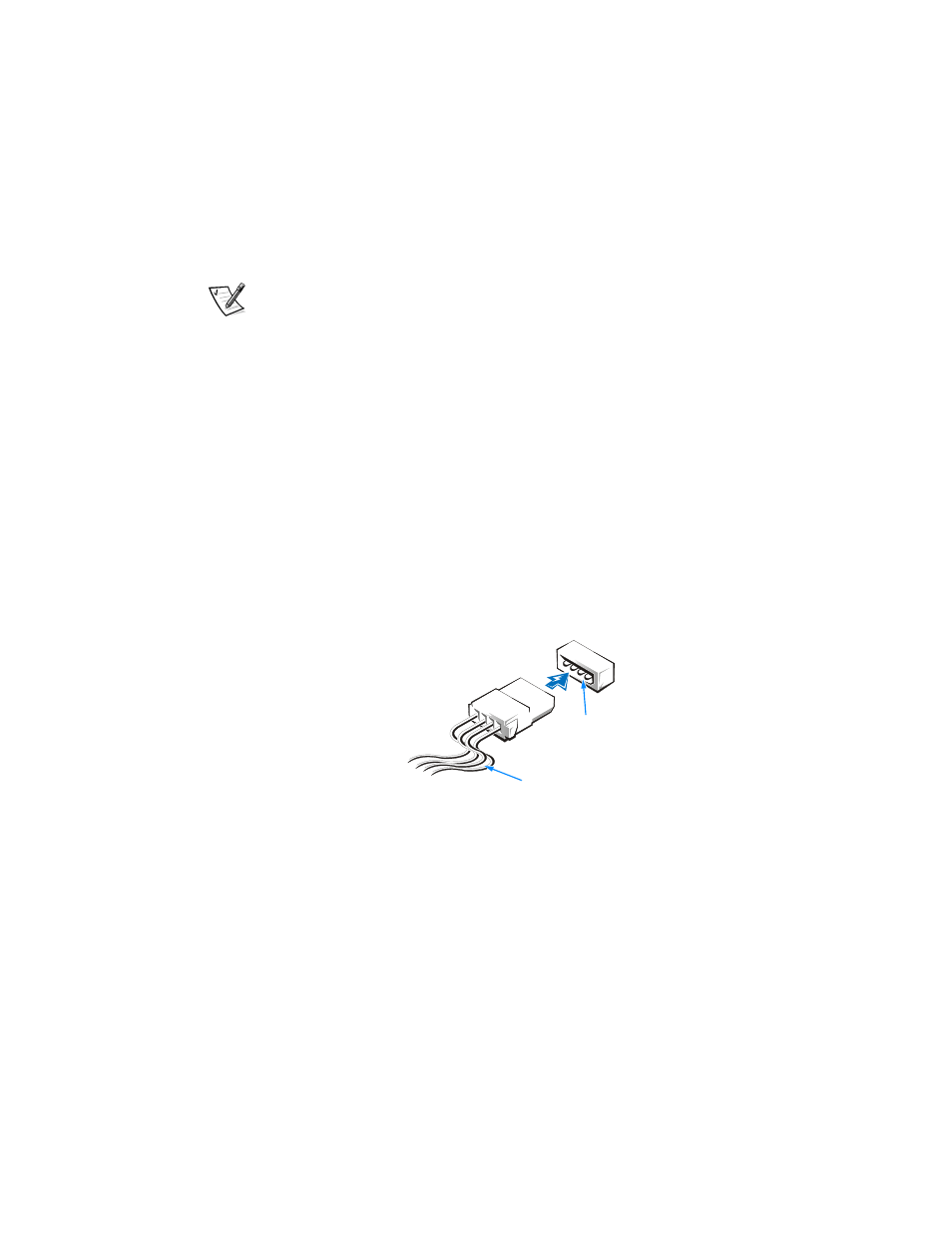
The DC power cable comes from the power supply and contains a 4-pin connector
that is keyed to avoid incorrect insertion. Do not force two connectors together if they
do not fit properly. Your drive’s power input connector (to which you connect the DC
power cable) resembles the connector shown in Figure 3-
3-3.
Figure 3-3. DC Power Cable Connector
The interface cable is attached to an interface connector either on the system board or
on a controller card. The system board contains a diskette-drive interface connector
(labeled “FLOPPY”) and two E
EIDE interface connectors (a primary one labeled “PRI
IDE” and a secondary one labeled “SEC IDE”). The EIDE hard-disk drive connects to
the primary connector; EIDE devices such as CD-ROM drives
OM drives, Zip drives, or tape
drives connect to the secondary connector.
The connector on the interface cable is a header connector, as shown in Figure 3-4.
This connector is keyed for correct insertion. A b
A blocked hole on the cable connector
matches a missing pin on the drive connector.
power input
connector
DC power cable