Docking connector – Dell Inspiron 4150 User Manual
Page 31
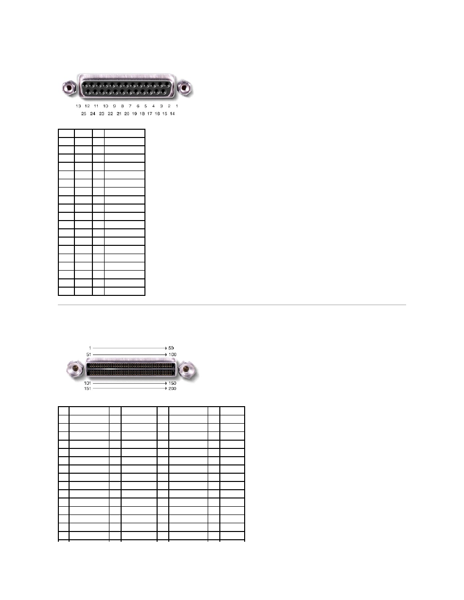
If you reconfigure your hardware, you may need pin number and signal information for the parallel connector.
Docking Connector
Use this connector to attach your computer to the optional docking device.
Pin
Signal I/O Definition
1
STB#
I/O Strobe
2
D0
I/O Printer data bit 0
3
PD1
I/O Printer data bit 1
4
PD2
I/O Printer data bit 2
5
PD3
I/O Printer data bit 3
6
PD4
I/O Printer data bit 4
7
PD5
I/O Printer data bit 5
8
PD6
I/O Printer data bit 6
9
PD7
I/O Printer data bit 7
10
ACK#
I
Acknowledge
11
BUSY
I
Busy
12
P E
I
Paper end
13
SLCT
I
Select
14
AFD#
O
Automatic feed
15
ERR#
I
Error
16
INIT# O
Initialize printer
17
SLIN# O
Select in
18-25 N/A
N/A Ground signal
Shell
N/A
N/A Frame ground
Pin Signal
Pin Signal
Pin Signal
Pin Signal
1
STRB#/5V
51
HSYNC
101 VGA_GRN
151 GND
2
PD0
52
VSYNC
102 GND
152 CLK_SPCI
3
PD1
53
GND
103 VGA_RED
153 GND
4
PD2
54
DOCKED
104 GND
154 SAD0
5
PD3
55
USB_VD1+
105 VGA_BLU
155 SAD1
6
PD4
56
USB_VD1-
106 DOCK_SD/MODE 156 SAD2
7
PD5
57
GND
107 D_IRTX
157 SAD3
8
PD6
58
USB_VD2+
108 D_IRRX
158 SAD4
9
PD7
59
USB_VD2-
109 GND
159 SAD5
10 GND
60
DOCKOC1#
110 SPIRQB#
160 SAD6
11 DOC_SPKR
61
RUN_ON#
111 SPIRQC#
161 GND
12 DOCK_MIC
62
GND
112 DAT_DDC2
162 SAD7
13 DOCK_LINE
63
NC
113 CLK_DDC2
163 SAD8
14 DOCK_CDROM
64
DOCK_SCLK
114 SPAR
164 SC/BE0#
15 GND
65
DOCK_LRCK
115 SPME#
165 SAD9