System board connectors – Dell PowerEdge VRTX User Manual
Page 66
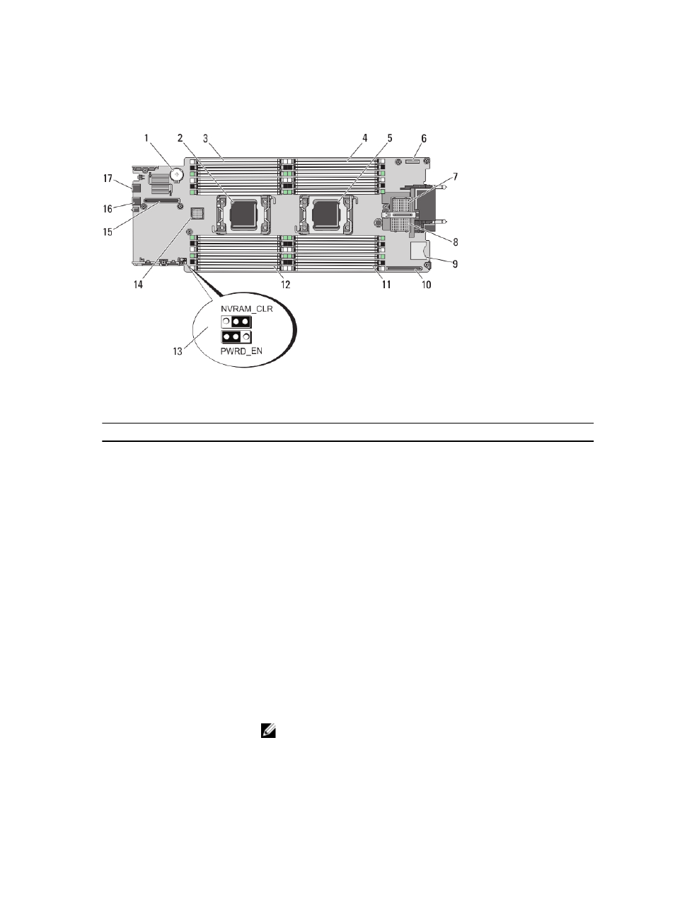
System Board Connectors
Figure 25. System Board Connectors
Table 5. System Board Connectors
Item
Connector
Description
1
BATTERY
Connector for the 3.0 V coin cell battery
2
CPU2
Processor socket 2
3
B3, B7, B11, B4, B8, B12
Memory module sockets (for processor 2)
4
A1, A5, A9, A2, A6, A10
Memory module sockets (for processor 1)
5
CPU1
Processor socket 1
6
MANAGEMENT RISER
Management riser card connector
7
MEZZ1_FAB_C
PCIe Mezzanine card connector for Fabric C
8
MEZZ2_FAB_B
PCIe Mezzanine card connector for Fabric B
9
vFLASH
SD vFlash card connector
10
NETWORK DAUGHTER
CARD
Network daughter card connector
11
A3, A7, A11, A4, A8, A12
Memory module sockets (for processor 1)
12
B1, B5, B9, B2, B6, B10
Memory module sockets (for processor 2)
13
PWRD_EN, NVRAM_CLR
System configuration jumpers
NOTE: Access requires removal of system board.
14
HD_BP
Hard-drive/SSD backplane connector
66
- PowerEdge RAID Controller H700 (178 pages)
- PowerEdge RAID Controller H700 (56 pages)
- PowerEdge RAID Controller H700 (200 pages)
- PowerVault TL4000 (2 pages)
- PowerVault TL2000 (176 pages)
- PowerVault TL2000 (16 pages)
- PowerVault TL2000 (3 pages)
- PowerVault TL2000 (116 pages)
- PowerVault 130T DLT (Tape Library) (49 pages)
- PowerVault TL2000 (1 page)
- PowerVault 110T DLT VS80 (Tape Drive) (49 pages)
- PowerVault TL2000 (22 pages)
- PowerVault TL4000 (306 pages)
- PowerVault TL2000 (2 pages)
- PowerEdge 800 (28 pages)
- PowerEdge 800 (58 pages)
- PowerEdge 800 (87 pages)
- PowerEdge 800 (24 pages)
- PowerEdge 800 (82 pages)
- PowerEdge 800 (2 pages)
- PowerEdge 800 (27 pages)
- PowerEdge 6400 (86 pages)
- PowerVault 124T (73 pages)
- PowerVault 124T (65 pages)
- PowerVault 124T (4 pages)
- PowerVault 124T (79 pages)
- PowerVault 124T (2 pages)
- PowerVault 124T (64 pages)
- PowerVault 124T (56 pages)
- PowerVault 124T (66 pages)
- PowerVault 124T (57 pages)
- PowerVault 110T LTO (Tape Drive) (28 pages)
- PowerVault 124T (55 pages)
- PowerVault TL4000 (3 pages)
- PowerVault TL4000 (176 pages)
- PowerVault TL4000 (2 pages)
- PowerVault TL4000 (16 pages)
- PowerVault TL4000 (116 pages)
- PowerVault TL4000 (1 page)
- PowerVault TL4000 (66 pages)
- PowerVault TL4000 (22 pages)
- PowerEdge RAID Controller 6i (120 pages)
- PowerEdge RAID Controller 6i (156 pages)
- PowerVault 715N (Rackmount NAS Appliance) (30 pages)
- PowerVault 715N (Rackmount NAS Appliance) (42 pages)