Mini tower chassis – Dell Precision 330 User Manual
Page 6
Mini Tower Chassis
l
Removing the chassis intrusion switch
l
Replacing the chassis intrusion switch
Removing the Chassis Intrusion Switch (Mini Tower Chassis)
1. Turn off the computer and peripherals, disconnect them from their electrical outlets, wait at least 5 seconds, and then
remove the computer cover
.
2.
Remove the front panel
.
3.
Remove the AGP card brace
.
4.
Remove all expansion cards
.
5.
Remove the expansion-card guide
.
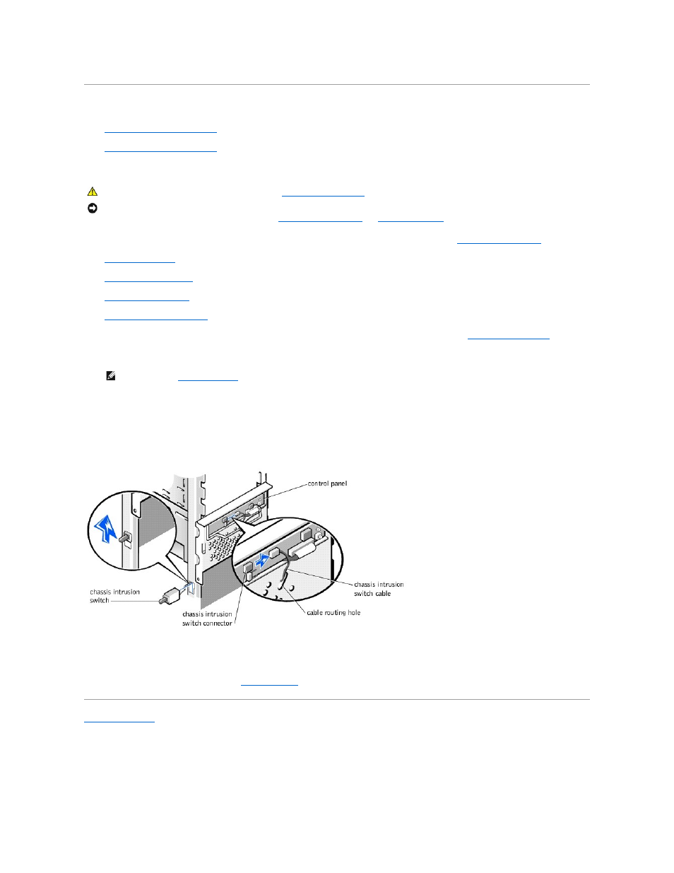
6. Disconnect the chassis intrusion switch cable from the control-panel connector (ALERT). To locate this connector, see "
Control Panel Components
."
7. Feed the chassis intrusion switch cable through the routing holes in the drive door and the front wall of the chassis (see the following figure).
8. Slide the chassis intrusion switch up out of its slot on the left side of the chassis.
9. Lift the chassis intrusion switch and switch cable away from the chassis.
Removing the Chassis Intrusion Switch (Mini Tower Chassis)
Replacing the Chassis Intrusion Switch (Mini Tower Chassis)
To replace the chassis intrusion switch, perform the
in reverse.
Back to Contents Page
CAUTION:
Before you perform this procedure, see "
Precautionary Measures
."
NOTICE:
Before disconnecting a peripheral from the system or removing a component from the system board, verify that the standby power indicator on the
system board has turned off. To locate this indicator, see "
System Board Components
" or "
Interior Service Label
."
NOTE:
You must
open the drive door
to feed the chassis intrusion switch cable through the cable routing holes. The switch cable routes through an
enlarged hole in the front chassis wall and through a hole in the drive door.