Control-panel cable cover, Front-panel i/o board, Removing the control-panel cable cover – Dell PowerEdge 2650 User Manual
Page 30: Replacing the control-panel cable cover, Removing the front-panel i/o board
Control-Panel Cable Cover
The control-panel cable cover shields the cable connected between the control panel board and the SCSI backplane board.
Removing the Control-Panel Cable Cover
1.
Turn off the system, including any attached peripherals, and disconnect the system from the electrical outlet.
2.
3.
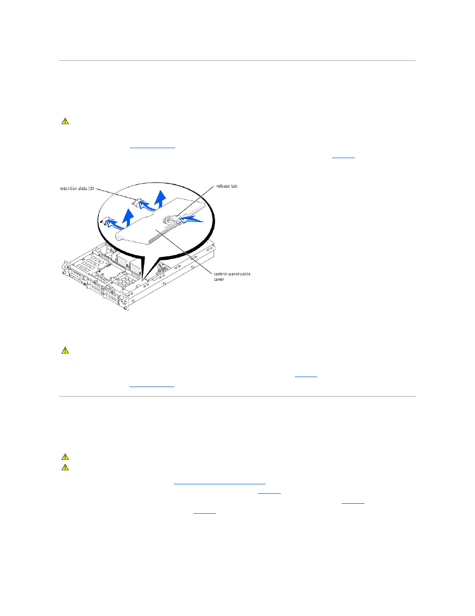
Press the release tab on the control-panel cable cover and lift the cable cover straight up to clear the chassis (see
Figure 4-5. Removing and Replacing the Control-Panel Cable Cover
Replacing the Control-Panel Cable Cover
1.
Align the retention tabs on the control-panel cable cover with the slots in the chassis.
2.
Lower the control-panel cable cover into the system until the cable cover snaps into position (see
).
3.
").
Front-Panel I/O Board
The front-panel I/O board provides connectors for PS/2 keyboard and mouse, video, and USB devices.
Removing the Front-Panel I/O Board
1.
Remove the control-panel cable cover (see "
Removing the Control-Panel Cable Cover
2.
Remove the two screws that secure the front-panel I/O board in the system (see
3.
Pull the front-panel I/O board away from the front panel to disconnect the I/O board from the control panel board (see
).
4.
Lift the front-panel I/O board out of the system (see
).
Figure 4-6. Removing and Replacing the Front-Panel I/O Board
CAUTION:
Before you perform this procedure, read the safety instructions in your System Information document.
CAUTION:
Before you perform this procedure, read the safety instructions in your System Information document.
CAUTION:
Before you perform this procedure, read the safety instructions in your System Information document.
CAUTION:
See "Protecting Against Electrostatic Discharge" in the safety instructions in your System Information document.