Power indicator codes, Panel features of the system, Table 3 – Dell PowerEdge 2650 User Manual
Page 8: Power-button indicator codes, Power-supply indicator codes
Power Indicator Codes
The system has indicators on the front panel and the power supplies that signify system power status.
Power-Button Indicator Codes
lists the power button indicator codes.
Power-Supply Indicator Codes
lists the power-supply indicator codes.
Figure 3-4. Power-Supply Indicators
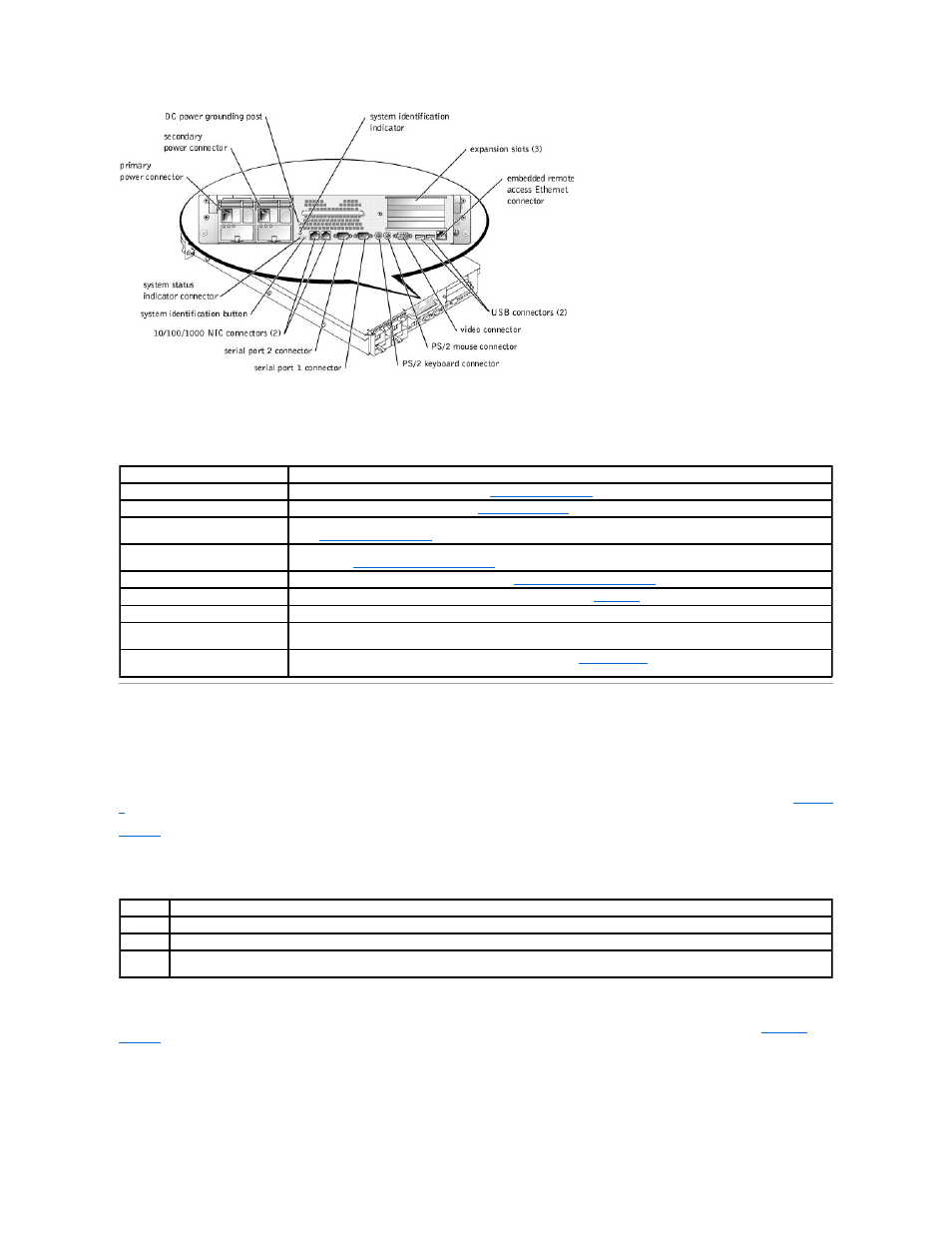
Table 3-3. Back-Panel Features
Component
Description
Power supply indicators
Provides information on power status (see "
NIC indicators
Provides information on NIC status (see "
System status indicator connector
Connects to an indicator that can signify when the system is operating correctly or when the system needs attention
(see "
System identification indicator
Signifies when the system is operating correctly or when the system needs attention, and can identify a particular
system (see "
System Identification Indicators
").
System identification button
Can be used to identify a particular system (see "
System Identification Indicators
").
Expansion slots
The expansion cards are installed on the system's riser board (see
Figure 5
-4
to identify the expansion slots).
I/O ports and connectors
Attach peripheral devices to the system. For more information, see "I/O Ports and Connectors" in your User's Guide.
Embedded remote access Ethernet
connector
Used for remote system administration. For more information, see your systems management documentation.
Power connectors and grounding
post
Connects the system's power supplies to a power source (see "
Power Supplies
").
Table 3-4. Power-Button Indicator Codes
Indicator Indicator Code
On
Indicates that power is supplied to the system, and the system is operational.
Off
Indicates that no power is supplied to the system.
Blinking
Indicates that power is supplied to the system, but the system is in a standby state. For more information on standby states, see your operating
system documentation.