Carrier 62E User Manual
Page 37
37
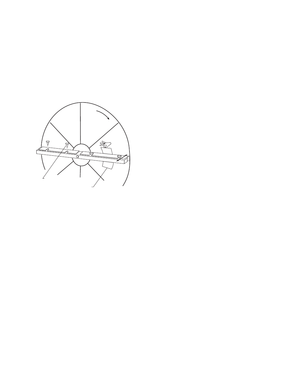
as a feeler gage, position paper between the wheel surface and
diameter seals. Adjust seals towards wheel surface until a slight
friction on the feeler gage (paper) is detected when gage is
moved along the length of the spoke. Retighten adjusting
screws and recheck clearance with “feeler” gage.
Wheel Drive Components —
The wheel drive motor
bearings are pre-lubricated and no further lubrication is neces-
sary. Make certain air cooling ports are not blocked.
The wheel drive pulley is secured to the drive motor shaft
by a setscrew. The setscrew is secured with removable adhe-
sive to prevent loosening. Annually confirm setscrew is secure.
The wheel drive belt is a urethane stretch belt designed to
provide constant tension through the life of the belt. No adjust-
ment is required. Inspect the drive belt annually for proper
tracking and tension. A properly tensioned belt will turn
the wheel immediately after power is applied with no visible
slippage during start-up.
Air Filters —
With this ERV unit and with most other
forced air heating, cooling and ventilation systems, regular air
filter maintenance is of utmost importance. Proper filter main-
tenance will improve indoor air quality, keep the building air-
handling system clean for peak efficiency, and prolong the life
of the HVAC (Heating, Ventilation, and Air Conditioning)
equipment. The life of the air filters is directly related to the ap-
plication to which the ERV unit is installed. The air filters
should be inspected every couple of weeks until a maintenance
schedule is established. The ERV unit is equipped from the fac-
tory with throwaway filters, however if the installer changed
the filter type, consult the installer for filter maintenance
instructions.
Replacing the Throwaway Filters —
After remov-
ing the service door (see Removing the Service Door section)
remove the spacer plugs and pull the filters or filter racks out of
the cabinet. Replace the filters with the original equipment
manufacturer replacements or equivalents. Refer to Tables 1A
and 1B for filter sizes.
Rotation
To
Adjust
Adjusting Screws
Feeler Gage
Fig. 39 — Diameter Seal Adjustment
A62-286ef