Power switching, Roomview, Example power switching application – Crestron electronic Green Light GLPS-HSW-FT User Manual
Page 24: Power net net senso r setup, Nor mal test cr es tr on, Ipa c-gl1, Vol - vol mut e on/off au x tape dss cd 2 fm cd
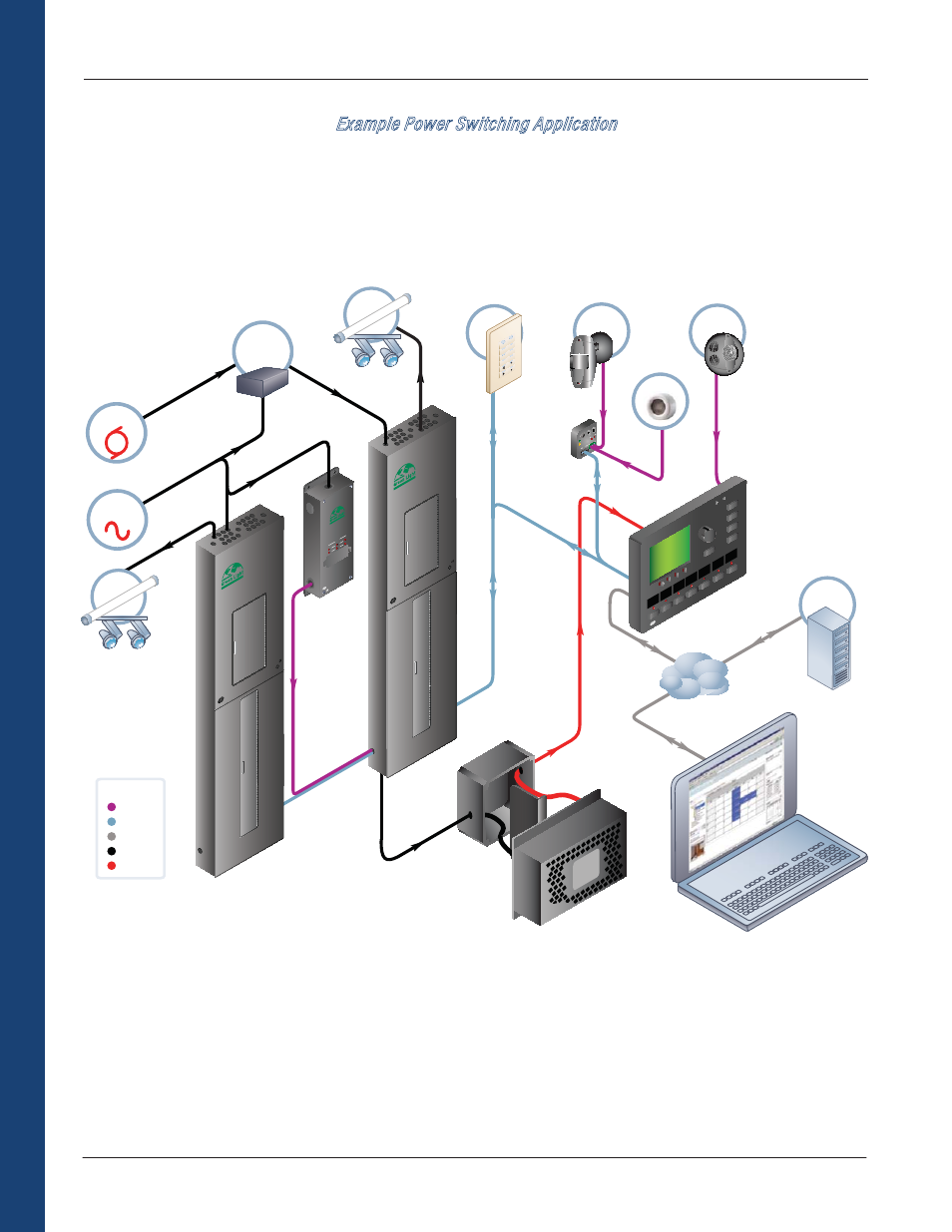
Example Power Switching Application
Below is an example power switching application with backup power operation using a GLS-PLS phase loss sensor (see accessories
section for more details). The power switching panels connect to an IPAC-GL1 processor via Cresnet. Connected to the processor are
various sensors, a keypad, and a photocell. It is possible to add up to two touchpanels to the IPAC-GL1 as well. Connected via a LAN is a
PC running RoomView. A GLA-PWS50 provides power to the processor.
Crestron Commercial Lighting Design Guide
20
Power Switching
POWER
NET
NET
SENSO
R
SETUP
CR
ESTR
ON
HI
LO
24 1
2 G
24
Y Z G
GLS-
SI
M
C
C
CRES
TR
ON
OCCUPANCY
Color Key
Control
AC
Cresnet
LAN
®
CR
ESTR
ON
ELECTRO
NICS
INC. R
OCKL
EIGH,
NJ 07647
USA
UL
®
GLS-PLS-120/277
Power
Loss
Sensor
Emergency Lighting Interface
PHASE
A
B
C
NOR
MAL
TEST
CR
ES
TR
ON
GENERATOR
ELECTRIC
UTILITY
EMERGENCY
TRANSFER
SWITCH
Normal Feed
Emergency Feed
Normal/Emergency Feed
GLS-PLS-
120/277
Phase
Loss
Sensor
®
CRESTR
ON
ELEC
TRONICS
INC. R
OCKL
EIGH, N
J 07647
USA
UL
IPA
C-GL1
Override
GLS-SIM
LAN
Normal Feed
24VDC
120 to 230VDC
GLA-PWS50
Power Supply
GLPS Power
Switching Panel
GLPS Power
Switching Panel
24VDC
CRESTRON
SENSOR
CRESTRON
SENSOR
VOL
-
VOL
MUT
E
ON/OFF
AU
X
TAPE
DSS
CD 2
FM
CD
KEYPAD
RoomView
TM
RoomView
SERVER
CRESNET
24VDC
LAN
LAN
LAN
PHOTOCELL
PHOTOCELL
AC
CRITICAL
LIGHTING
AC
NON-CRITICAL
LIGHTING