Canopen communication, Communication profile, Canopen message structure – Baumer GNAMG User Manual
Page 7
Manual_GNAMG_CANopen_EN.doc
7/41
Baumer IVO GmbH & Co. KG
21.11.12
Villingen-Schwenningen, Germany
3.3. CANopen communication
3.3.1. Communication profile
Communication between network users and master (PC / control) is effected by object directories and objects.
Adressing the objects is by help of a 16bit index. The individual communication objects are standardized by
CANopen communication profile DS 301. They are subdivided into several groups:
• Process DataOobjects PDO for process data transmission in realtime
• Service Data Objects SDO for write and read access to the object directory
• objects for synchronisation and error warnings of CAN users:
SYNC-object (synchronisation object) for synchronisation of network users
EMCY-object (emergency object) for error warnings of a single device or its periphery
• Network Management NMT (network management) for initialization and network control
• Layer Setting Services LSS for configuration by serial number, revision number etc within the existing
network
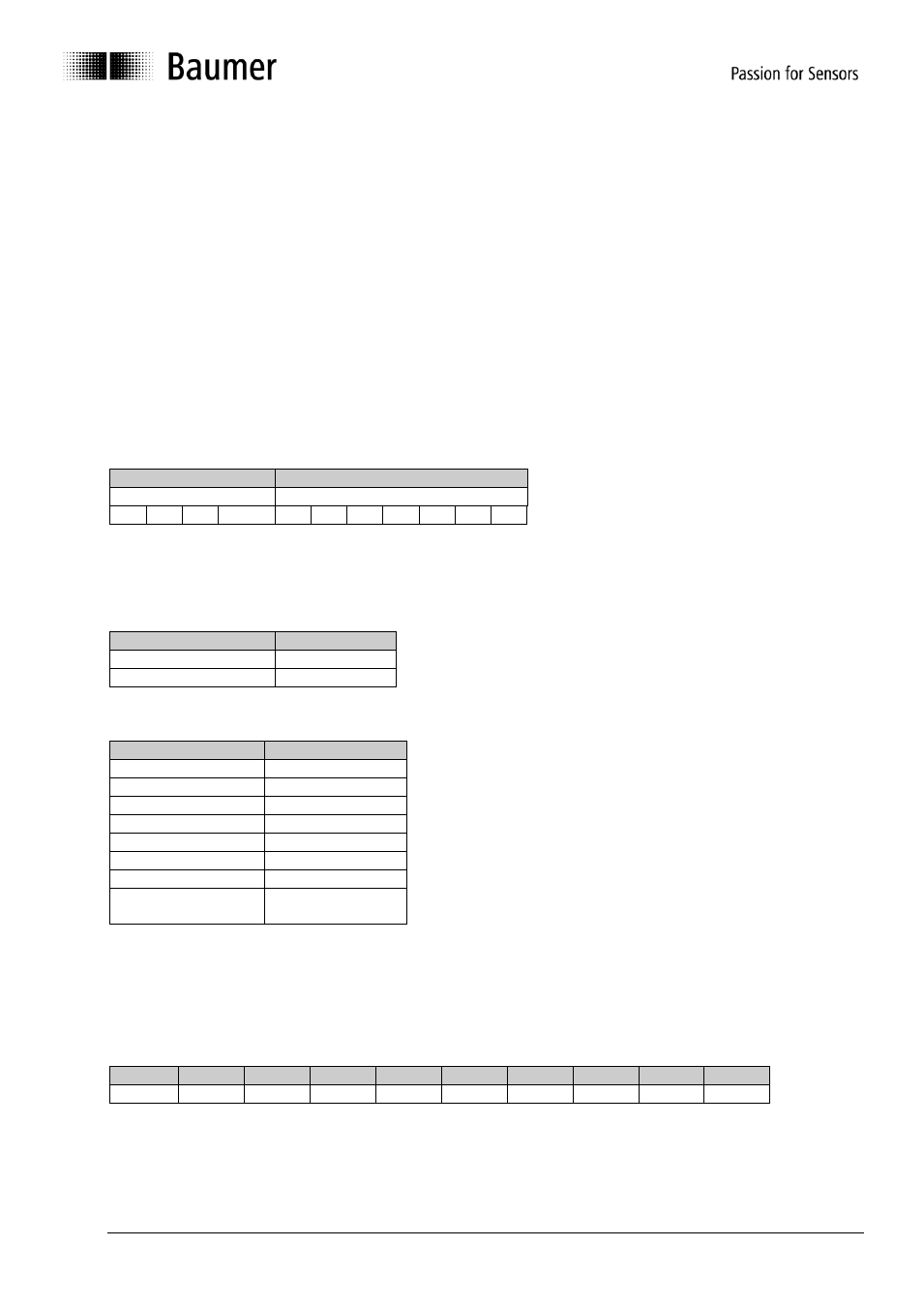
3.3.2. CANopen message structure
First part of the message is the COB-ID (identifier).
Structure of the 11-Bit COB-ID :
Function Code
Node-ID
4 Bit Function code
7 Bit Node-ID
The function code is defining the kind of message and priority. The lower the COB-ID, the higher the priority of
the message.
Broadcast messages:
Function code
COB-ID
NMT
0
SYNC
80h
Peer to Peer messages:
Function code
COB-ID
Emergency
80h + Node-ID
PDO1 (tx)
1)
180h + Node-ID
PDO2 (tx)
1)
280h + Node-ID
SDO (tx)
1)
580h + Node-ID
SDO (rx)
1)
600h + Node-ID
Heartbeat
700h + Node-ID
LSS (tx)
1)
7E4h
LSS (rx)
1)
7E5h
1): (tx) and (rx) from the inclination sensor
’s point of
view
The Node-ID is optionally set anywhere between 1 and 127 via the CANopen bus (if rotary switch = 0). Default
setting of the inclination sensor is Node ID 1.
Changing the Node-ID is effected by using service data object 2101h or by LSS.
A CAN telegram consists of the COB-ID and a data packet of max. 8 bytes:
COB-ID DLC
Byte 1
Byte 2
Byte 3
Byte 4
Byte 5
Byte 6
Byte 7
Byte 8
Xxx
x
xx
xx
xx
xx
xx
xx
xx
xx
More detailed information on the telegram structure in later chapters.