Terminal assignment, Status leds (status indicators) – Baumer GNAMG User Manual
Page 41
Manual_GNAMG_CANopen_EN.doc
41/41
Baumer IVO GmbH & Co. KG
21.11.12
Villingen-Schwenningen, Germany
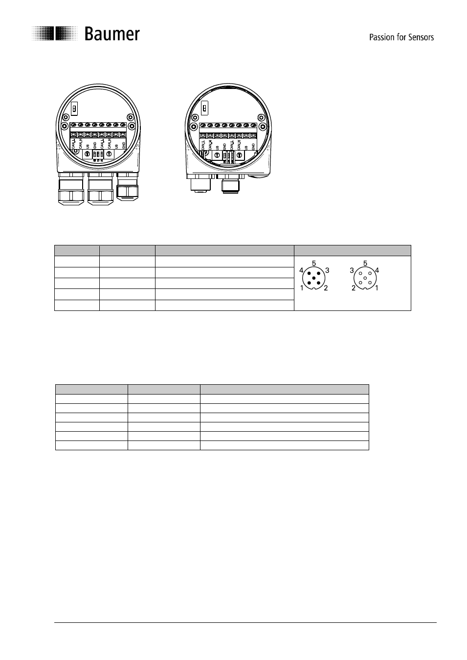
View inside the inclination sensor
Cable gland
M12 connector
6.2.5. Terminal assignment
Pin
Terminal
Explanation
M12-connector (male/female)
1
GND
Ground connection relating to UB
2
UB
Supply voltage 10...30 VDC
3
GND
Ground connection relating to UB
4
CAN_H
CAN Bus signal (dominant High)
5
CAN_L
CAN Bus signal (dominant Low)
Terminals with the same designation are connected to each other internally and identical in their functions.
Maximum load on the internal clamps UB-UB and GND-GND is 1 A each.
6.3. Status LEDs (status indicators)
An integrated DUO-LED is provided on the back of inclination sensor housing.
LED green
LED red
Status
Off
Off
No supply voltage
Flashing
Off
Pre-operational Mode
On
Off
Operational Mode
On
On
Stopped/Prepared Mode
Off
Flashing
Alert/warning
Off
Off
Error
- UNAR 18U6912/S14G (2 pages)
- UZAM 70P8131/S14C (3 pages)
- UZDK 30P6113 (2 pages)
- O500.GR-GW1T.72CU (4 pages)
- URAM 50N1721 (2 pages)
- FVDK 22P6101/S14C (2 pages)
- FZAM 30P5004 (2 pages)
- OZDK 10P5150/S35A (2 pages)
- FPDK 20N5101/S35A (2 pages)
- UNDK 20N6903/S35A (2 pages)
- UZAM 50N6121/S14 (2 pages)
- IFBR 17N17T1/S14L-9 (2 pages)
- OPDM 16P5102 (2 pages)
- OPDK 14P5901/S14 (2 pages)
- OEDK 14P5101/S35A (2 pages)
- OBDM 12N6910/S35A (4 pages)
- MTRM 16G2524/M300 (2 pages)
- UR18.DA0-UA1B.7BO (4 pages)
- GK473 (31 pages)
- GK473 (16 pages)
- GK473 (32 pages)
- GK473 (24 pages)
- UNDK 30N1713/S14 (2 pages)
- FKDM 22P1911/S14F (4 pages)
- UNDK 09G8914/D1 (3 pages)
- Speed switches DSL (22 pages)
- OADM 20U2480/S14C (4 pages)
- FZCK 07N6901 (2 pages)
- FVDK 12P6410/S35A (2 pages)
- G1-G2-G0-GE-GB-GXxxx (18 pages)
- G1-G2-G0-GE-GB-GXxxx (52 pages)
- G1-G2-G0-GE-GB-GXxxx (26 pages)
- URDK 10N8914 (2 pages)
- OPDK 14P3902/S35A (2 pages)
- UNAM 30U9103/S14 (2 pages)
- PA203 (30 pages)
- O300.RP-PV1T.72N (4 pages)
- BMxx, GBxxx-GXxxx - EtherCAT / PoE from version ,5.0 (30 pages)
- OADM 12U6430/S35A (4 pages)
- OADM 13U7580/S35A (4 pages)
- O500.RP-NV1T.72CU (4 pages)
- FHDK 14N6901/S35A (2 pages)
- O500.RP-PV1T.72CU (4 pages)
- OZDK 10P5150 (2 pages)
- G1-G2-GB-GXxxx (40 pages)