2 description of ssi encoder – Baumer G1-G2-GB-GXxxx User Manual
Page 40
Manual_ProGeber_V1-40_EN.doc 40/40
Baumer IVO GmbH & Co. KG
10.05.11
Villingen-Schwenningen,
Germany
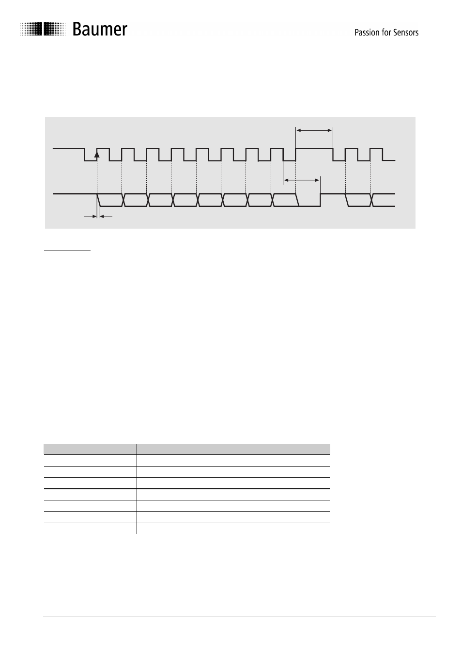
6.2 Description of SSI encoder
The SSI (Synchronous Serial Interface) transmits the position value serially, i.e. bit by bit from
the encoder to the control. The transmission works according to the following scheme:
1
2
3
4
5
6
7
8
Takt
MSB
Dn
Dn-1
Dn-2
Dn-3
D3
D2
D1
D0
Tp
Tm
9
Tv
LSB
Description
Mono-flop time T
m
:
20 µs (adjustable)
Delay time T
v
:
Delay time pulse edge until data output max. 300 ns
Pulse space T
p
:
min.
25
µs
Data bit Dn:
MSB
Data bit D1:
LSB (or special bits)
In the closed-circuit state, the data and pulse lines are at High level (+5 V). The transmission is
started by the first trailing edge. With the corresponding following rising edge, the data bits are
output to the data line one after the other. The MSB makes the start. If the number of pulses is
higher than the number of data bits, only zeros will be sent after the data bits.
After the end of the pulse sequence, the data lines are kept at Low level (0 volt) during the
mono-flop time Tm.
For the wiring, it is recommended to use data and pulse lines which are twisted in pairs. In
case of lengths of lines exceeding 100 m, the data and pulse lines should have a minimum
cross section of 0.25 mm² and the supply voltage line of 0,5 mm². The range of the pulse rate
is between 62,5 kHz and 1,5 MHz. The maximum length of line depends on the SSI pulse
frequency and should be adapted to the following table:
Length of line
Highest admissible SSI pulse frequency
12,5 m
810 kHz
25 m
750 kHz
50 m
570 kHz
100 m
360 kHz
200 m
220 kHz
400 m
120 kHz
500 m
100 kHz