Connect the power cord and communications cable – Bio-Rad CFX Automation System II User Manual
Page 17
Chapter 1: CFX Automation System II Installation
| 9
CFX Automation System II
| 9
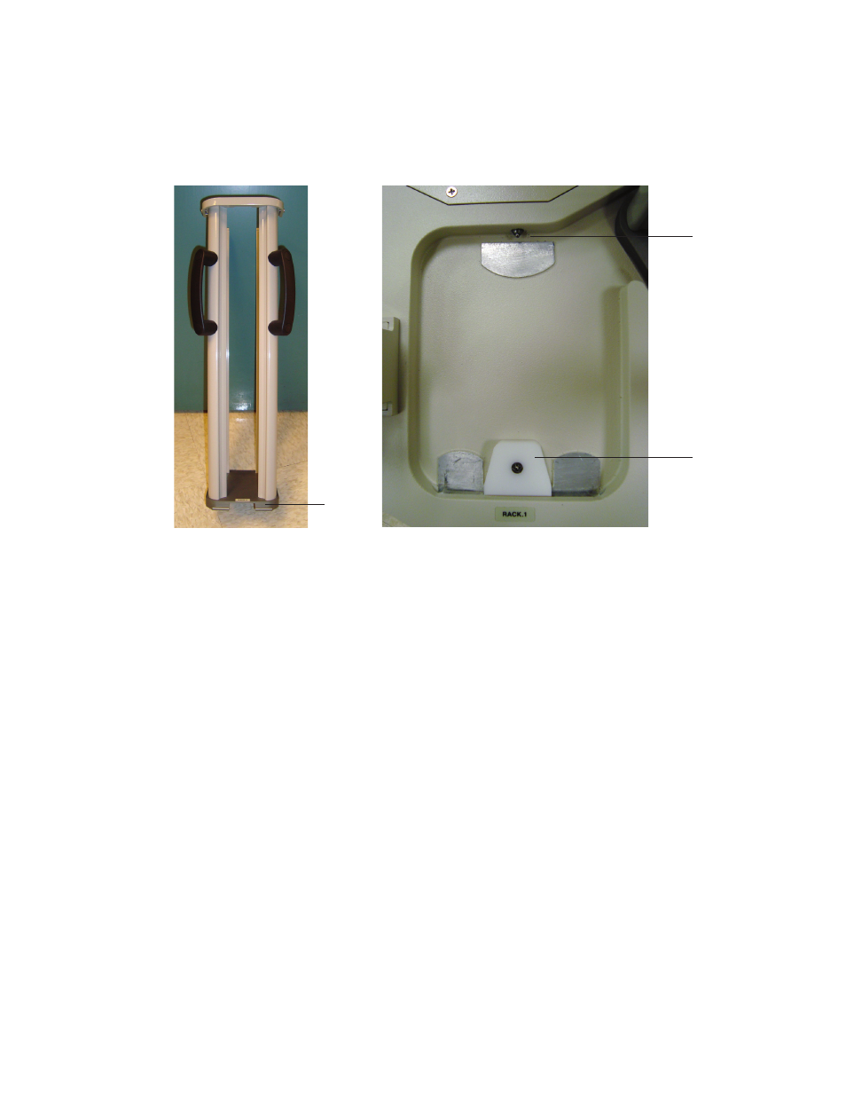
4. Place the rack locator notch under the lip of the rack position (Figure 9).
5. Maintain the placement of the rack under the lip while you lean the rack backward and
snap it into place against the locator pin.
6. Before releasing the rack, make sure it is firmly secured under the lip by gently pulling it
toward you. Release gently in order to maintain the proper position.
Note: If the rack is not correctly placed under the lip, the rack will not be level. This will
misalign the racks and the plate handler will not function properly.
7. Verify the region of the plate handler that holds the racks is level relative to the CFX
System(s). Place the bubble level at the bottom of each empty rack. Compare the position
of the bubble when the level is placed in the racks, in the tower, and on the CFX System(s)
block(s). If the racks are not level, adjust the plate handler foot assemblies so that all regions
of the plate handler are as level as possible, relative to the CFX System(s) (see Level the
Plate Handler).
To remove a rack, reverse the steps above.
Connect the Power Cord and Communications Cable
WARNING! Before proceeding, verify the plate handler power switch is OFF and the computer
power cord is unplugged.
1. Connect one end of the USB cable to the USB connector on the back of the plate handler
(Figure 10).
2. Connect the other end of the USB cable to an available USB port on the computer.
Fig. 9. Rack securing position.
LIp
Locator pin
Locator
notch