Amico SSM Monitor Arms (Side to Side) User Manual
Page 9
www.amico.com
6
WARNING:
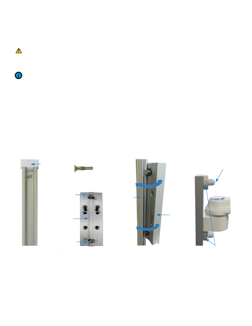
To prevent the V-Adapter from falling down the channel, ensure that the screws are fastened as tight
as possible. Rotate SSM arm side to side after installation to verify no movement is present between the adapter
and the rail.
NOTE:
Before installation, ensure two nuts and two knobs are loose to the tip of the V-adapter screws. This will
allow the head of the V-adapter screws to adjust into the profiles of the Vertical Rail.
1. Angle the SSM arm from either side and guide the heads of the top and bottom screws into the channel of the
rail
(Figure 1-3)
2. Ensure the flange on the adapter is properly aligned with the rail.
3. Position the arm to the desired height and fasten two knobs and two nuts (12 mm) to the tightest possible
position. Cover the nuts with the two plastic caps provided.
(Figure 4)
(Figure 1)
Vertical Rail
End cap
(Figure 4)
Tighten thumb
screws and nuts
Screw Knobs
Mounting to the VRS (Vertical Rail System)
(With the V-Adapter)
(Figure 3)
Side of the
V-adapter
Side of
the VRS
(Figure 2)
Side view
V-adapter screw
Backside of the V-adapter
Head of the
bottom screw
Head of the
top screw
Flange