Amico SSM Monitor Arms (Side to Side) User Manual
Page 8
5
Amico Accessories
Mounting to the Hill-Rom Rail (with the G-Track Adapter (GTA))
WARNING:
To prevent the adapter from falling down the channel, ensure that the screws are
Secured to the tightest possible position. After the installation, rotate the SSM arm side to side and verify no
movement is present between the adapter and the rail.
WARNING:
Removal of lock nuts will require a new set for reinstallation. Please contact Amico Accessories for
spare parts, 1-877-264-2697
NOTE:
Before installing, ensure two regular nuts and 2 lock nuts are loosened to the tip of the G-adapter screws.
This will allow the head of the G-adapter screws to adjust into the profile of the Hill-Rom rail
(Figure 3).
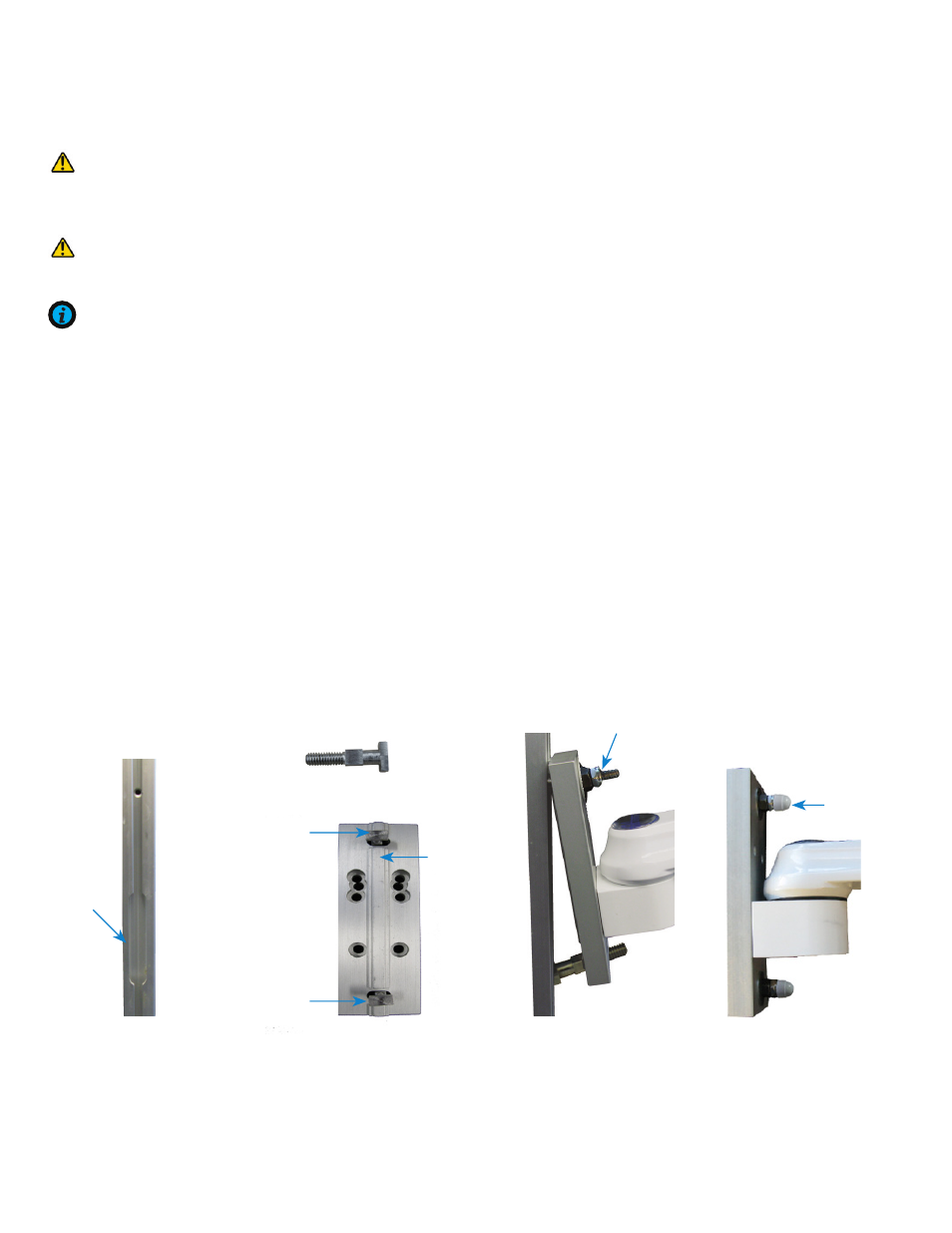
1. Support the bottom of the SSM arm and guide the head of the top screw into the opening of the rail
(Figure 1 and 2)
.
2. Ensure the flange on the GTA is properly aligned with the rail. Slide the GTA up so that the head of the bottom
screw slides into the opening of the rail
(Figure 3)
.
3. Position the SSM arm to the desired height. Tighten the 2 regular nuts and then the 2 lock nuts on the top and
bottom of the adapter using a 12 mm wrench.
4. Cover the nuts with the two plastic caps provided
(Figure 4)
.
(Figure 4)
Plastic caps
(Figure 3)
12 mm nuts, lock nuts
Side of the G-Adapter
(Figure 1)
Opening of
the rail
Hill-Rom Vertical Rail
Head of the
bottom screw
Head of the
top screw
Flange
(Figure 2)
Backside of the GTA
Side view
G-adapter screw