Great Plains NP30A 30-foot Predelivery Manual User Manual
Page 37
Great Plains Manufacturing, Inc.
Final Setup
33
08/30/2011
407-313Q
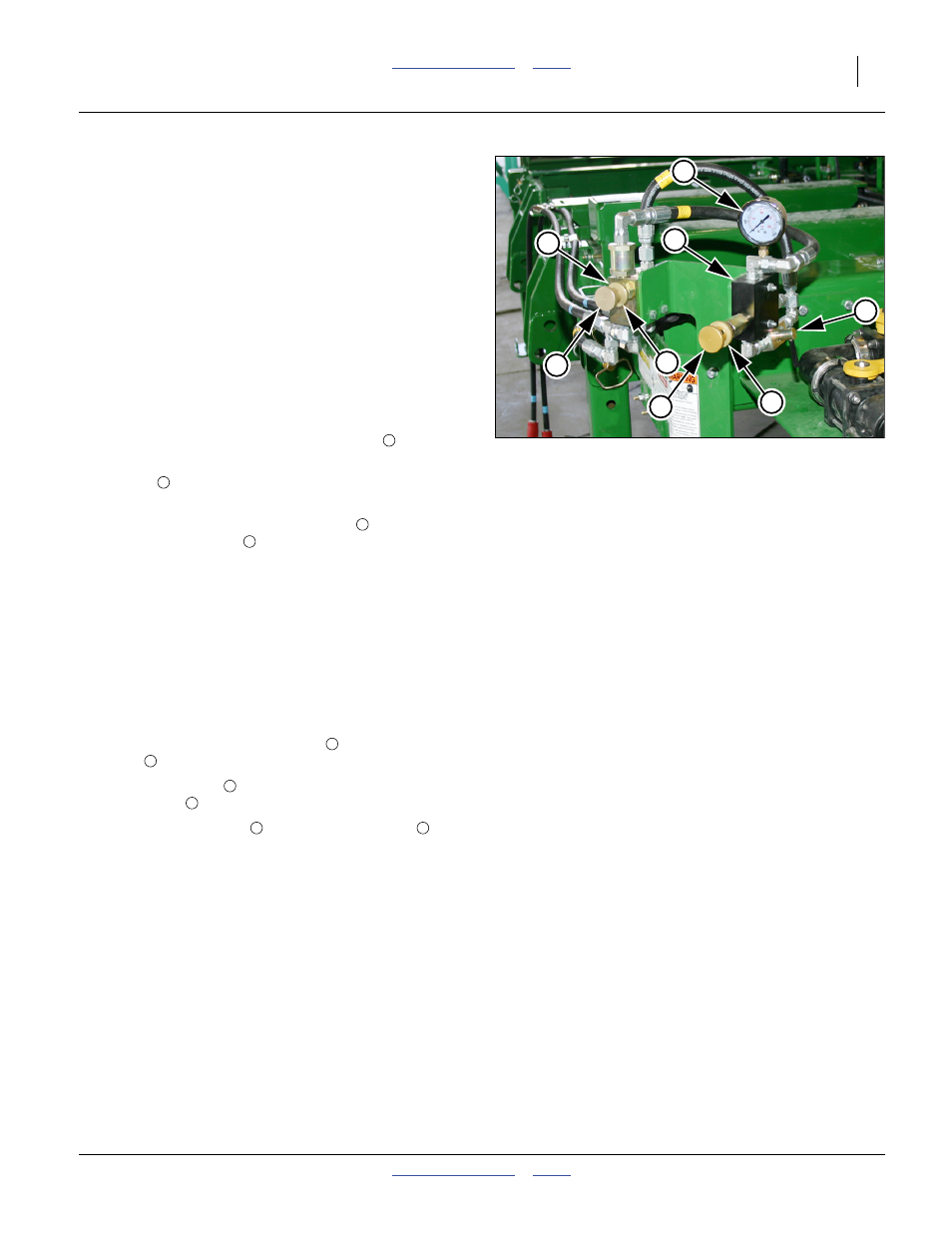
Adjust the weight transfer to achieve consistent coulter
depth, while keeping the wings level with the center sec-
tion. If insufficient weight is transferred, outside (wing)
coulters may run higher than center section. If too much
weight is transferred, center section may run high.
If adjusted when the tractor is cold, re-adjustment may
be required when the oil warms. Monitor the pressure
gauge during early field operations.
Refer to Figure 44 on page 32 and Figure 46
160. In field conditions, unfold, lower implement, and set
or check application depth (see Operator manual for
these steps).
161. Pull forward to put coulters in ground.
162. Put tractor in Park and set parking brake.
163. Open the weight-transfer shut-off valve
.
164. If this is a 2-Point implement, close the lift-assist
valve ( in Figure 44 on page 32) by turning the
knob fully clockwise.
165. Release the bypass valve lock disc
. Turn the
bypass valve knob
fully clockwise to shut-off all
bypass oil flow. Tighten lock disc.
166. Set tractor to half throttle. Adjust tractor flow control
valve so that wings fold/unfold at a reasonable
speed. Keep tractor running for step 167 through
step 170.
Note: On 2-point implements, fold and unfold are followed
by lift and lower operations.
167. Set tractor remote circuit for unfold. Lock lever for
continuous operation.
168. At the pressure reducing valve
, release the lock
disc
.
169. Adjust the knob
for an initial value of 800 psi on
the gauge
. Tighten the lock disc.
170. At the bypass valve
, release the lock disc
.
Adjust the bypass valve knob counter-clockwise
until the pressure reading just begins to fall from the
value set at step 169. Turn the knob clockwise
1
⁄
4
turn. Tighten the lock disc.
171. Observe implement operation, and re-adjust down-
pressure as necessary after oil warm-up. Repeat
step 167 through step 170. The bypass valve needs
to be closed prior to any adjustment to increase
weight transfer.
Figure 46
Weight Transfer Adjustment
32041
3
4
6
5
4
7
8
2
2
2
6
3
3
8
5
4
2