Install delivery tubing – Great Plains NP30A 30-foot Predelivery Manual User Manual
Page 31
Great Plains Manufacturing, Inc.
Install Components
27
08/30/2011
407-313Q
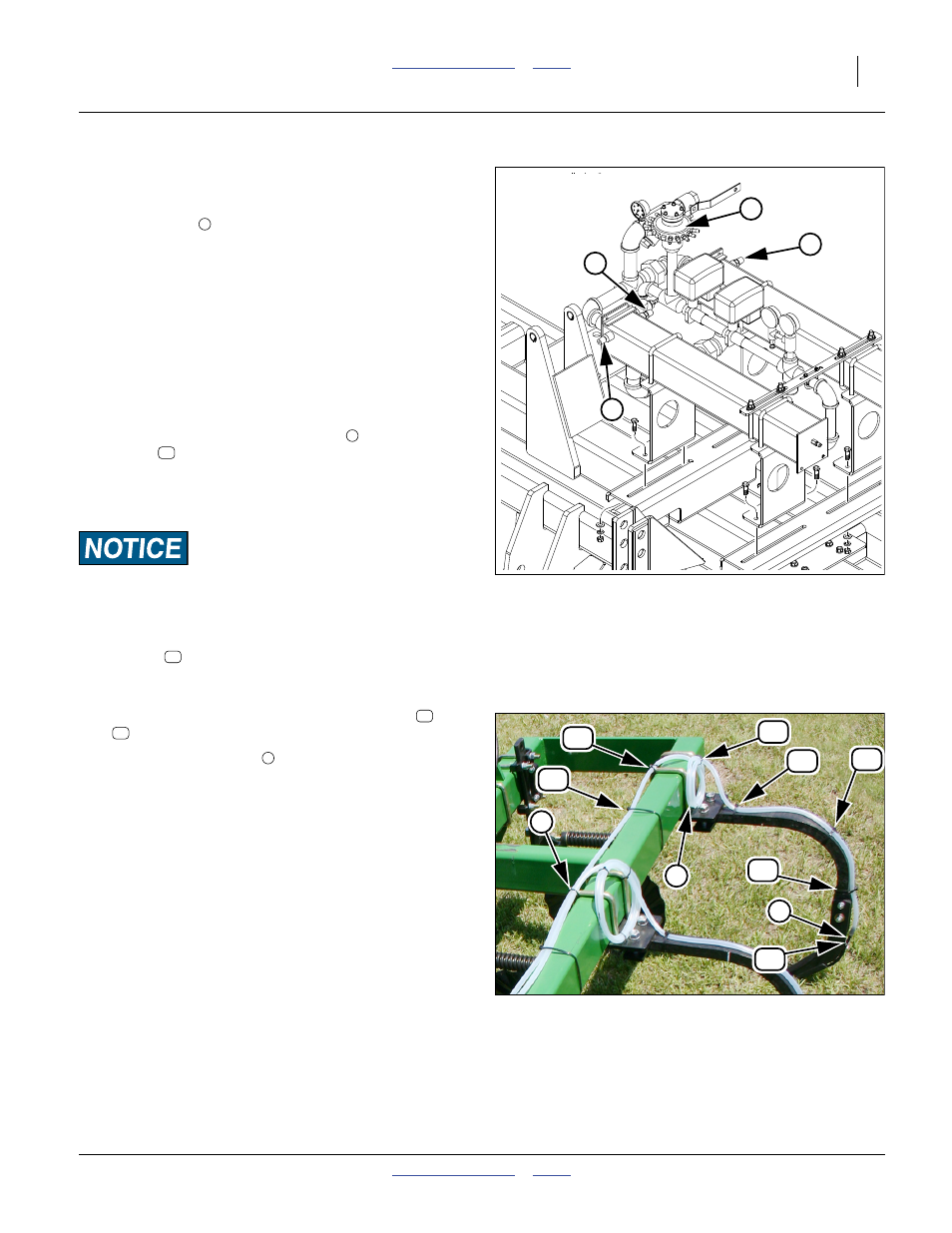
Install Delivery Tubing
Refer to Figure 36 and Figure 37
The NH
3
3
⁄
8
in EVA tubing is to be run from the Impelli-
cone flow divider
to the shank knives.
Note: It may be necessary to fold and unfold the machine
and take note of the extra length needed for tubing
in the hinge pivot areas so the hoses do not bind or
pinch when folding or unfolding the machine.
130. Starting with the knife located furthest from
Impellicone flow divider, run the
3
⁄
8
in EVA tubing
from the flow divider along the frame tubing to the
knife shank, making allowances for frame fold-up in
the hinge pivot areas.
131. Run the tubing down the shank under the closer
and attach to the knife outlet tube
with the hose
clamp
.
Note: Before securing this first hose, measure the total
length and record. Cut all remaining knife tubes to
this furthest length.
Rate Imbalance Risk:
It is very important that all knife tubes are cut to the same
length as the longest hose to maintain equal rate to each knife.
132. Coil any excess tubing inboard of the shank. Secure
with tie
. Secure all other ties. Do not overtighten.
Avoid crushing or cutting the tubing.
133. Continue to run each vapor tube, securing to the
rear frame tubes and shanks with cable ties
and
as needed.
Two vapor overflow outlets
exist on each cooler. These
outlets are
3
⁄
4
in EVA tubing and are run to the dual outlet
knives on the center section.
134. Attach the
3
⁄
4
in EVA tubing to the outlet hose barbs
on the Accuflow coolers and run the tubing to the
larger outlet tube on the knives. Secure the tubing in
the same manner as the
3
⁄
8
in EVA tubing.
Continue at “Install Nurse Tank Hitch” on page 29.
Figure 36
Impellicone Flow Divider
32773
5
4
5
5
4
5
44
41
Figure 37
End Row Tubing (Anhydrous)
31712
1
2
44
41
41
41
41
40
40
3
40
41
5