Install pull-type wing gauge wheels – Great Plains NP30A 30-foot Predelivery Manual User Manual
Page 27
Great Plains Manufacturing, Inc.
Install Components
23
08/30/2011
407-313Q
Install Pull-Type Wing Gauge Wheels
Installation is slightly different for right wing and left wing.
The left side cylinder rod has a depth stop assembly.
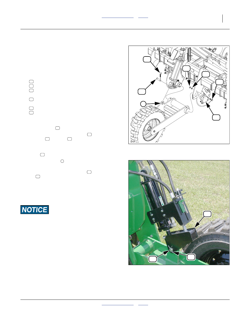
Refer to Figure 29 (depicting a center section mount - the
right wing mount install is identical)
105. At each wing gauge wheel mount where a wheel/
arm assembly is to be installed, remove and save
six sets of:
803-021C NUT HEX 5/8-11 PLT
804-022C WASHER LOCK SPRING 5/8 PLT
802-057C HHCS 5/8-11X2 1/4 GR5
two:
161-040D AXLE TUBE BUSHING MACH.
and one set of:
2A0134 MW COTTER PIN
805-124C PIN CLEVIS 1 X 3 11/16 GR5 PLT
106. Guide a wheel arm tube into alignment with the
mount holes. Secure the alignment by re-inserting
the axle tubes
.
107. Secure the axle tubes with bolts
, lock
washers
and nuts
.
Refer to Figure 30
108. For the left gauge wheel, rotate the depth stop
clevis
so that it is to the front.
109. Align the arm lug
with the clevis of the cylinder
rod.
110. Secure rod clevis with clevis pin
and cotter
pin
.
111. Repeat step 106 through step 109 for remaining
gauge wheel.
Do not exercise the lift hydraulics at this time.
Do not install wing gauge wheel lift lock channels.
Machine Damage Risk:
Never install a lock channel on the depth stop cylinder unless
the clevis has been rotated clear of the cylinder rod. Lowering
the implement onto a lock channel with the clevis in place will
damage the clevis.
Figure 29
Hydraulic Gauge Wheel
31705
12
49
64
57
67
17
3
57
64
49
12
17
67
12
49
64
57
19
Figure 30
Hydraulic Depth Stop
31521
67
17
19
67
17