Liquid fertilizer drop lines (option), Install caps on taps, Install drop lines to rows – Great Plains YP825A Operator Manual User Manual
Page 173: Install caps on taps install drop lines to rows
Great Plains Manufacturing, Inc.
Appendix C - Initial Setup
169
2014-08-15
401-651M
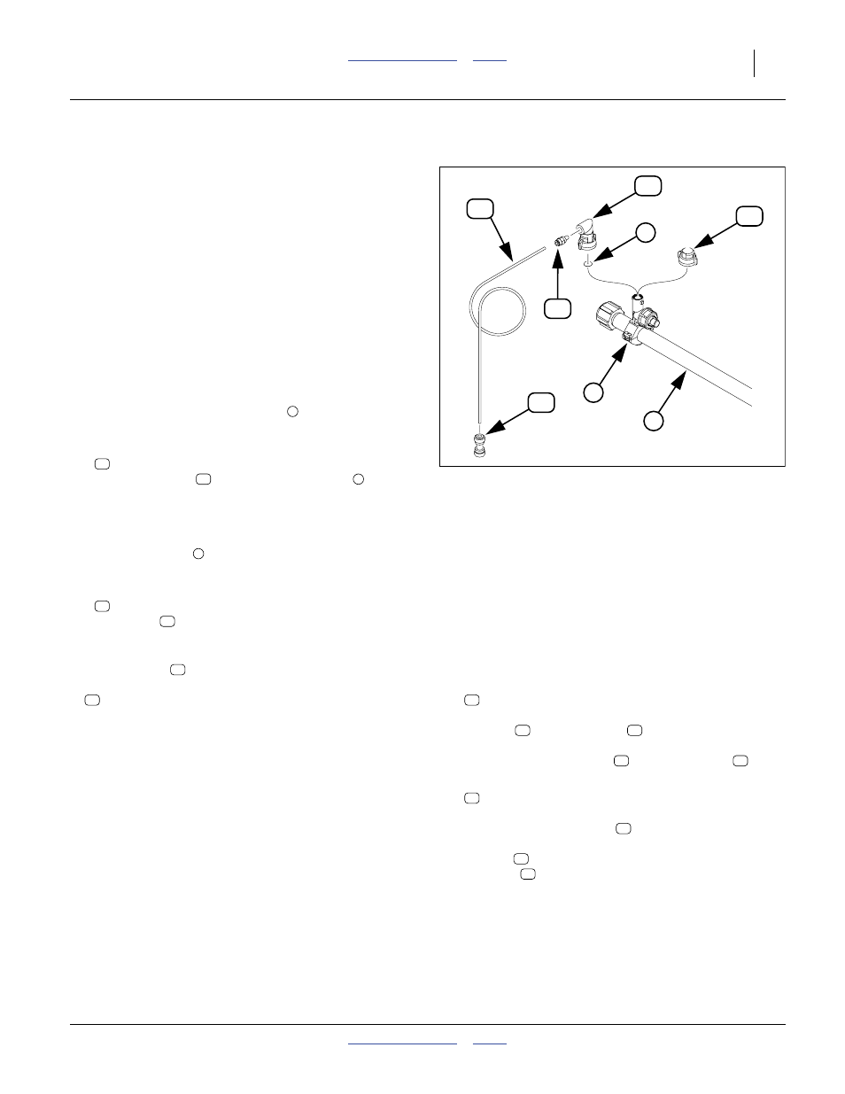
Liquid Fertilizer Drop Lines (Option)
Booms are identical for single-row and twin-row planters.
For single-row use, and if planting single-row on a
twin-row planter, half of the nozzles are shut off.
Drop lines are not factory-installed, and may not be
dealer-installed, because there can be multiple possible
applicator connection points, including:
• frame-mounted coulter applicator
• 25AP Series nut bar applicator
• seed firmer applicator
• press wheel dribbler
Install Caps on Taps
Determine which manifold taps
and which shut off.
2.
For each active row, select one:
832-051C NOZZLE CAP QUICK X 90X1/4 FNPT
Align the nozzle
with the manifold tube
down and rotate 90
°.
Note: Nozzles may face forward or back, at user
preference.
Note: Orifice plates
may be installed prior to capping, if
the size is known.
3.
For each shut-off row, select one:
832-042C
NOZZLE SHUT OFF CAP W/ GASKET
Press cap
down and rotate 90
°.
Install Drop Lines to Rows
Drop line tubing
is supplied on one or more uncut
coils:
990-109R TUBE NYLON 1/4OD X 062WL
Lengths are cut for each active nozzle.
4.
Route tubing and cut. Routing goals are:
5.
At the nozzle end, if the tubing adaptors are not
already installed, select one:
800-367C AD PUSH 1/4TUBEX1/4MNPT
Apply liquid pipe thread sealant. Thread the
adaptor
into the nozzle
.
Insert the drop line tube
into the adaptor
.
6.
At the application end, select one:
830-383C CP 1/4 PUSH LOK POLY
Confirm that the coupler
is required for, and
compatible with, the style of applicator. Push the
coupler
onto the applicator tube. Push the drop
line tube
into the coupler.
Note: When the coupler is not used, typically with
1
⁄
2
inch O.D. steel applicator tubes, push the drop
line tubing entirely through the applicator tube,
leaving
1
⁄
2
inch to
3
⁄
4
inch of tubing length
exposed. Tie wrap the tubing near the top of the
applicator tube.
Figure 156
Drop Line Detail
31002
74
1
75
3
2
78
65
73
1
75
75
2
74
74
• Allow slack at the nozzle for nozzle removal and
orifice plate changes.
• Route to avoid planter moving parts which could
cause tubing damage.
• Route for continuous down slope - avoid low spots
in tubing.
• Allow slack along the route to anticipate coulter or
row unit vertical range of motion.
• Secure the tubing with tie-wraps only where
planter operations can’t cause tubing movement.
78
78
65
65
75
78
65
73
73
73
78