Connect manifold to pump, Pre-delivery closeout – Great Plains YP825A Operator Manual User Manual
Page 166
162
YP425A, YP625A and YP825A
Great Plains Manufacturing, Inc.
401-651M
2014-08-15
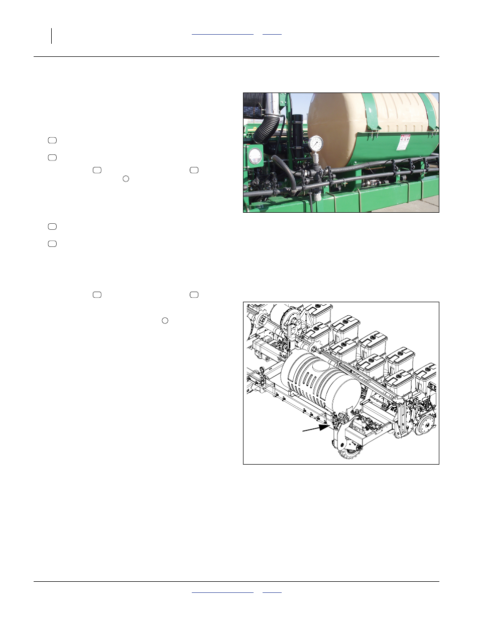
Connect Manifold to Pump
This page applies only to planters:
(YP425 s/n B1009N+)
(YP625 s/n B1044Q+) (YP825A s/n B1015S+)
Refer to Figure 144
57. Select one:
990-081R HOSE 3/4 ID 200PSI EPDM
and two:
800-123C CLAMP WRM DRV #16 SS (.68-1.5)
58. Slip a clamp
on each end of the hose
. Secure
one end to the elbow
at the manifold, and the
other to the
3
⁄
4
in hose barb adaptor on the left side of
the valve cross fitting.
Refer to Figure 144 and Figure 145
59. Select one:
990-082R HOSE 1 ID 200PSI EPDM
and two:
800-123C CLAMP WRM DRV #16 SS (.68-1.5)
60. Route the hose as follows:
YP425A: directly from valve to pump
YP625A: along center tube and behind left tank
YP825A: along center tube and behind left tank
61. Slip a clamp
on each end of the hose
. Secure
one end to the 1in hose barb adaptor on the right
side of the valve cross fitting. Secure the other end to
the elbow at the top of the pump
.
If the customer has specified row connection points,
boom outlet orifice plates, nozzle caps and drop lines
may be installed at this time. See page 169.
Pre-Delivery Closeout
62. Check that all working parts are moving freely, bolts
are tight, and cotter pins are spread.
63. Check that all grease fittings are in place and
lubricated. See “Lubrication” on page 110.
64. Check that all safety decals and reflectors are
correctly located and legible. Replace if damaged.
See “Safety Decals” on page 6.
65. Inflate tires to pressure recommended and tighten
wheel bolts as specified. See “Tire Inflation Chart”
on page 137.
66. For immediate delivery, move all uninstalled items
(such as the manuals, orifice plates and clean-out
container) from crates to the hoppers at the left side
of the planter. Otherwise, place them in a
well-marked container and store securely.
Figure 146
Manifold to Relief Valve (S/N+)
31994
77
64
64
77
1
76
64
Figure 147
Pump Drive
29929
64
76
2