Assemble mounts, Mount boom, Install relief valve/gauge assembly – Great Plains YP825A Operator Manual User Manual
Page 164: There is one more used at step 42
160
YP425A, YP625A and YP825A
Great Plains Manufacturing, Inc.
401-651M
2014-08-15
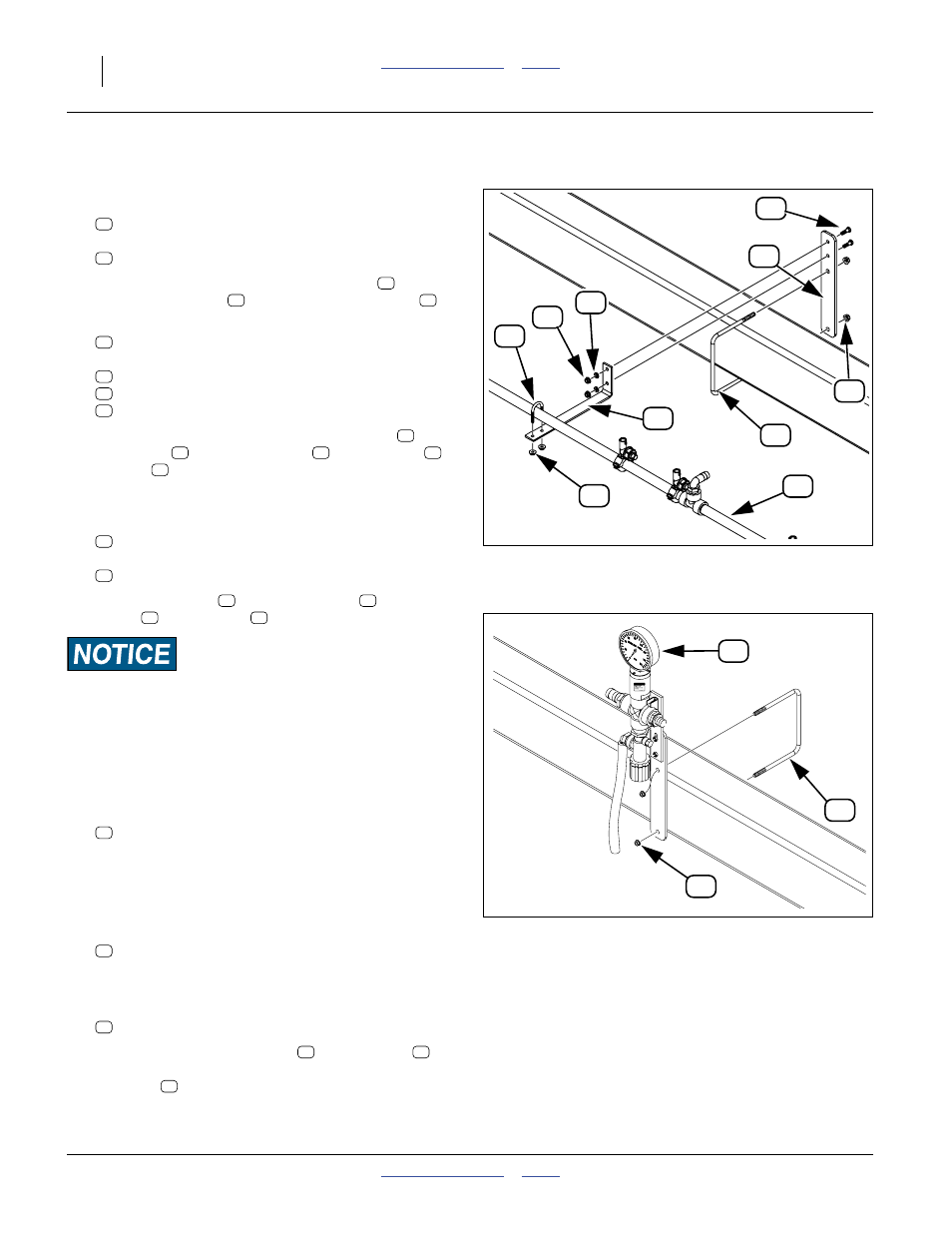
Assemble Mounts
Refer to Figure 142
36. Select two (YP425A) or four (YP625/825A):
407-389D WET BOOM U-BOLT PLATE
and four or eight:
803-068C NUT HEX FLANGE 3/8-16 PLT
37. With the 3-hole end up, place each plate
on the
threads of a U-bolt
. Secure with flange nuts
.
38. Select two (YP425A) or four (YP625/825A):
407-137D FERTILIZER BOOM MOUNT
and four or eight sets of:
802-159C HHCS 5/16-18X1 GR5
804-009C WASHER LOCK SPRING 5/16 PLT
803-008C NUT HEX 5/16-18 PLT
39. With the short break up, attach each mount
to
each plate
. Secure with bolt
, lock washer
and nut
.
Mount Boom
40. Select two (YP425A) or four (YP625/825A):
806-152C U-BOLT 1/4-20 X 1.125 X 2 RND
and four or eight:
803-088C NUT HEX LOCK 1/4-20 FLG
41. Secure the boom
over each mount
with a
U-bolt
and lock nut
.
Equipment Damage Risk:
Do not over-tighten. Tighten lock nuts only enough to prevent
manifold tube from rotating. If you tighten to normal
1
⁄
4
-20
torque spec, the tube is likely to be crushed.
Install Relief Valve/Gauge Assembly
Refer to Figure 143
42. Select one:
806-150C U-BOLT 3/8-16 X 7 1/32 X 6 GR5
43. Position the U-Bolt by planter model:
YP425A: right of left-most manifold U-bolt.
YP625A: left of center tube
YP825A: left of center tube
44. Select one:
829-104C GAUGE 100 PSI 4IN STAINLESS
which is factory pre-assembled to a gauge protector,
cross-fittings, relief valve, dump line and mount.
45. Select two:
803-068C NUT HEX FLANGE 3/8-16 PLT
46. Position the gauge assembly
on the U-bolt
,
gauge on top, facing forward. Secure with flanged
lock nuts
.
63
68
61
69
71
66
55
67
62
70
Figure 142
Boom Mount Detail
31968
63
68
63
70
68
62
66
55
67
62
63
66
55
67
71
69
72
70
68
Figure 143
Relief Valve Detail
31002
61
62
71
69
70
72
68
72
70
68