Great Plains 3N-4025P Operator Manual User Manual
Page 61
4/23/2010
196-286M
59
Adjustments
Disk Adjustment
Marker disks may be sharp. Use caution when making
adjustments in this area.
Refer to Figure 88
There are two ways you can change the mark left
by the marker disk.
1.
Disk Angle. To change angle of cut, loosen
1/2-inch bolts holding disk assembly. Rotate
disk assembly as desired.
2.
Direction of Cut. To change direction of cut
and throw dirt either in or out:
a.
Reverse blade and depth band by re-
mounting lug bolts on disk hub.
b.
Reverse angle of assembly by removing
two 1/2-inch bolts holding disk assembly.
Turn disk assembly one-half turn. Rein-
stall 1/2-inch bolts and set disk angle.
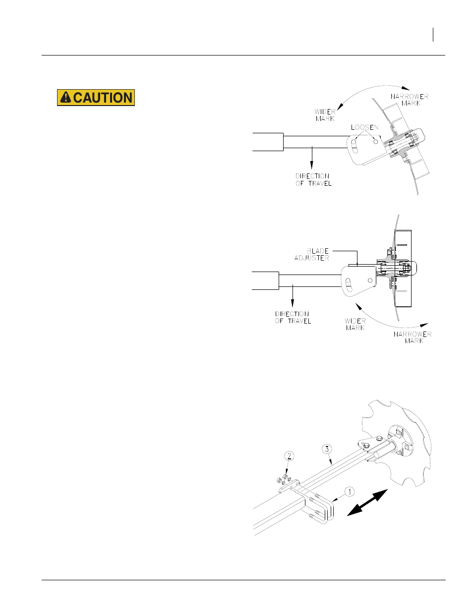
Marker Width
Refer to Figure 89
To adjust marker width, loosen nuts (2) on
U-bolts (1). Move marker disk tube (3) in or out to
get the proper adjustment.
To measure for marker width adjustment:
1.
Lower drill in the field and drive forward a few
feet.
2.
Measure from the middle of the outside row to
the mark in the ground made by marker disk.
3.
Adjust as needed.
Figure 88
Marker Disk Blade Adjustment
11757
11248
Disk Angle
Direction of Cut
Figure 89
Marker Width Adjustment
20315