Connect seed hoses, Install fan outlet hose, Connect seed hoses install fan outlet hose – Great Plains 3PYP Predelivery Manual User Manual
Page 39: Step 117)
Planter Assembly 35
07/19/2011
401-312Q
Connect Seed Hoses
112. To ease the connection process, mark the free end
of each hose with its Tube number and Port assign-
ment. Check that each hose has a clamp.
Tubes are numbered from T01 (bottom row, planter
left) to T12 or T16 (top row, planter right).
Air box manifold ports are numbered from P01
(planter left) to P16 (planter right).
Obtain the Tube-to-Port assignment from the tables
on page 33 (12 port) or page 34 (16_port).
113. Remove any shipping caps on the manifold ports.
On a 12 port planter, ports P01, P02, P15 and P16
are unused, and have caps secured with clamps.
Leave these caps in place.
Refer to Figure 62
The free ends of the flexible seed hoses are guided
under the frame tube but above the steering gear.
It is generally easier to start at the center manifold ports
(P08 and P09), and work outwards.
114. Slide each hose fully onto its assigned manifold
port.
115. Slide the clamp toward the end of the hose and
secure it at
3
⁄
4
in (1.9cm) from the face of the air box.
116. Repeat step 114 and step 115 for all hoses.
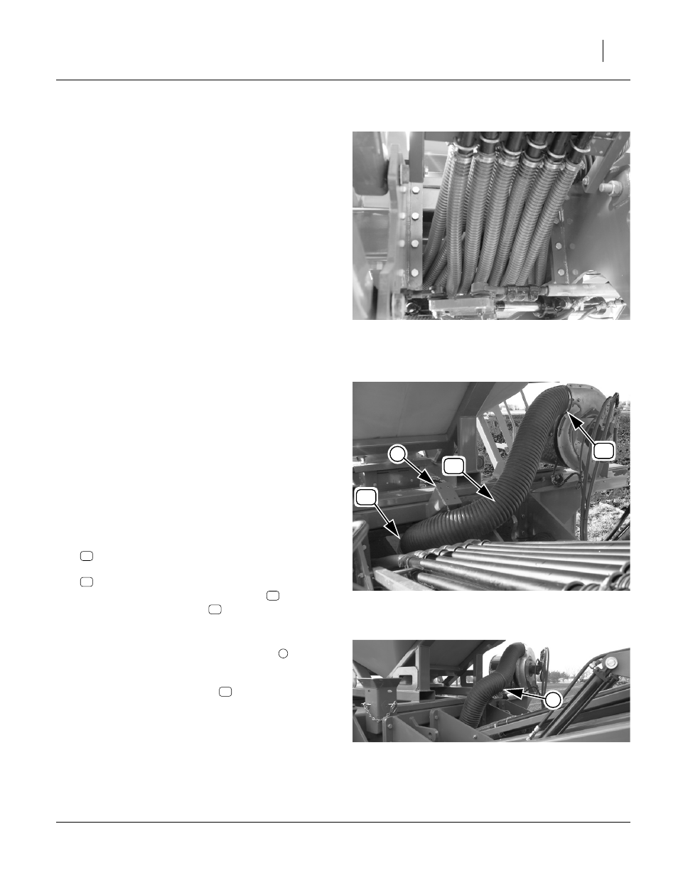
Install Fan Outlet Hose
Refer to Figure 63 and Figure 64
117. Select the:
816-601C HOSE 6 IN X 56 AIR
with two:
800-151C CLAMP WRM DRV #96SS (4.75-6.5)
Attach the flexible fan discharge hose
to the out-
let of the fan with a clamp
.
118. Route the hose
over the left parallel arms,
across the face of the unused weldment
,
to the inlet of the distribution box.
Length of hose may require some trimming. Attach
hose to box inlet with clamp
.
119. Secure the hose to the weldment face with cable
ties.
Note: If the hose is allowed to fall below the weldment, it
may be crushed during use.
FigureSpacer:
Figure 62
Rack Seed Hoses
29173
T06
T01
FigureSpacer:
Figure 63
Fan Outlet Hose
29172
50
21
21
4
50
21
50
21
FigureSpacer:
Figure 64
Fan Hose Secured
29210
4
4
21