Install casters, Identify caster arms, Install left caster arm – Great Plains 3PYP Predelivery Manual User Manual
Page 27: Identify caster arms install left caster arm
Planter Assembly 23
07/19/2011
401-312Q
Install Casters
Determine how to lift move and align the caster arms
with the available lifting equipment. The illustrations in
these instructions depict the arms clamped to a lift fork.
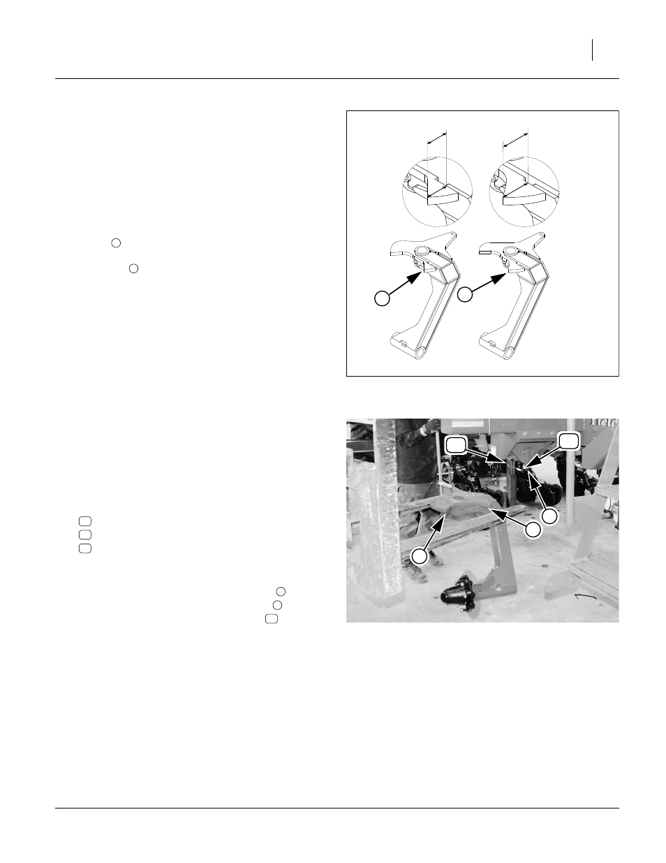
Identify Caster Arms
Refer to Figure 40
48. Identify the left and right caster arms. Right and left
orientation is critical for mounting hydraulic steering.
To distinguish between right and left: notice the right
caster
distance from the arm to the tip of the stop
(pie-shaped) measures 3.79 inches wide and on the
left caster
the distance from arm to tip of stop
(pie-shaped) is narrower measuring 2.97 inches.
49. Before installing the caster arms, check that both
spindles have a cross bolt and thrust washer.
Install Left Caster Arm
Refer to Figure 41
50. Carefully secure the left arm to a lift or hoist capable
of holding the arm with the pivot hole vertical, and
remaining clear of the seed structure while position-
ing the arm.
51. At the cart, remove and save one set of:
803-026C NUT LOCK 3/4-10 PLT (not shown)
802-360C HHCS 3/4-10X6 1/2 GR5
804-102C PIVOT THRUST WASHER
Coat the spindle with anti-seize compound.
52. Align the arm under the spindle with the arm to the
inside and the hub trailing. The turn stop
to the
rear of the spindle must fit in the cut-out
in the
arm top plate. Place the thrust washer
on the
spindle before the spindle contacts the arm.
53. Fully raise the arm on the spindle. If the spindle
rises, tap it down with a rubber mallet.
FigureSpacer:
Figure 40
Caster Arms
25372
1
2
2.97 in.
3.79 in.
R
L
FigureSpacer:
Figure 41
Move Left Caster Arm to Spindle
29153
7
6
7
31
47
37
31
47
6
7
47