Strainer adjustment, Ground drive: setting relief valve – Great Plains NP4000 40-foot Operator Manual User Manual
Page 75
Great Plains Manufacturing, Inc.
Fertilizer Rate
71
2012-03-28
407-776M
Strainer Adjustment
Refer to Figure 50
A Banjo brand strainer
is supplied with the ground
drive fertilizer pump. It is plumbed before the
CDS-John Blue pump. The standard 80 mesh screen
should be suitable for most applications. Other screen
sizes are available from Banjo Corporation.
If changing screen sizes, keep in mind the following.
• A smaller mesh (100) will keep very small manifold
orifice plates from plugging so often. However, the
screen will have to be cleaned more often.
• A larger mesh (50) or (30) will pass more material but
should only be considered when using large manifold
orifice plates.
• Mesh sizes below 30 are not recommended for use
with CDS-John Blue pumps.
• A plugged or partially plugged screen will starve the
pump resulting in a reduced application rate.
• Mesh sizes: (Smallest) 100, 80, 50, 30 (Largest)
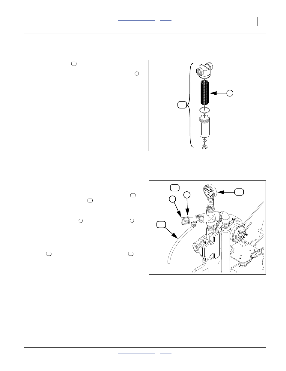
Ground Drive: Setting Relief Valve
A relief valve is plumbed after the ground drive pump
outlet to protect the manifold and pump from excessive
pressure. Any product that activates the relief valve
discharges from the dump line
.
To set relief valve:
Refer to Figure 51
1.
Unlock plastic jam nut
from relief valve knob
.
2.
Unscrew knob counter-clockwise until it loses
contact with internal spring.
3.
Screw knob clockwise two turns. Start at this setting.
4.
While operating in the field, observe manifold
gauge
, and watch for relief valve discharge
.
5.
If valve is dumping product and gauge reads under
65 psi, stop tractor and turn knob clockwise (looking
down)
1
⁄
4
turn. Continue operating at normal field
speed. Repeat this step as needed until no product
is discharged from relief valve.
6.
If pressure gauge reads above 65 psi, change to a
larger orifice. Go to step 2. Repeat steps.
Figure 50
Strainer
18418
1
18
18
1
Figure 51
Fertilizer Relief Valve
31729
2
3
24
26
25
{
25
26
2
3
24
26