Dismount one coulter connection – Great Plains NP4000 40-foot Operator Manual User Manual
Page 118
114
NP4000
Great Plains Manufacturing, Inc.
407-776M
2012-03-28
Dismount One Coulter Connection
If your side dress kit included a coulter, continue at
“Install Side Dress Coulter” on page 115.
18. Set aside one removed coulter for side dress use.
Refer to Figure 68
19. At the rear tool bar, remove and save one:
149-584D COULTER CLAMP 6H X 4W
four sets:
804-022C WASHER LOCK SPRING 5/8 PLT
803-021C NUT HEX 5/8-11 PLT
and two:
806-016C U-BOLT 5/8-11 X 6 1/32 X 5 3/4
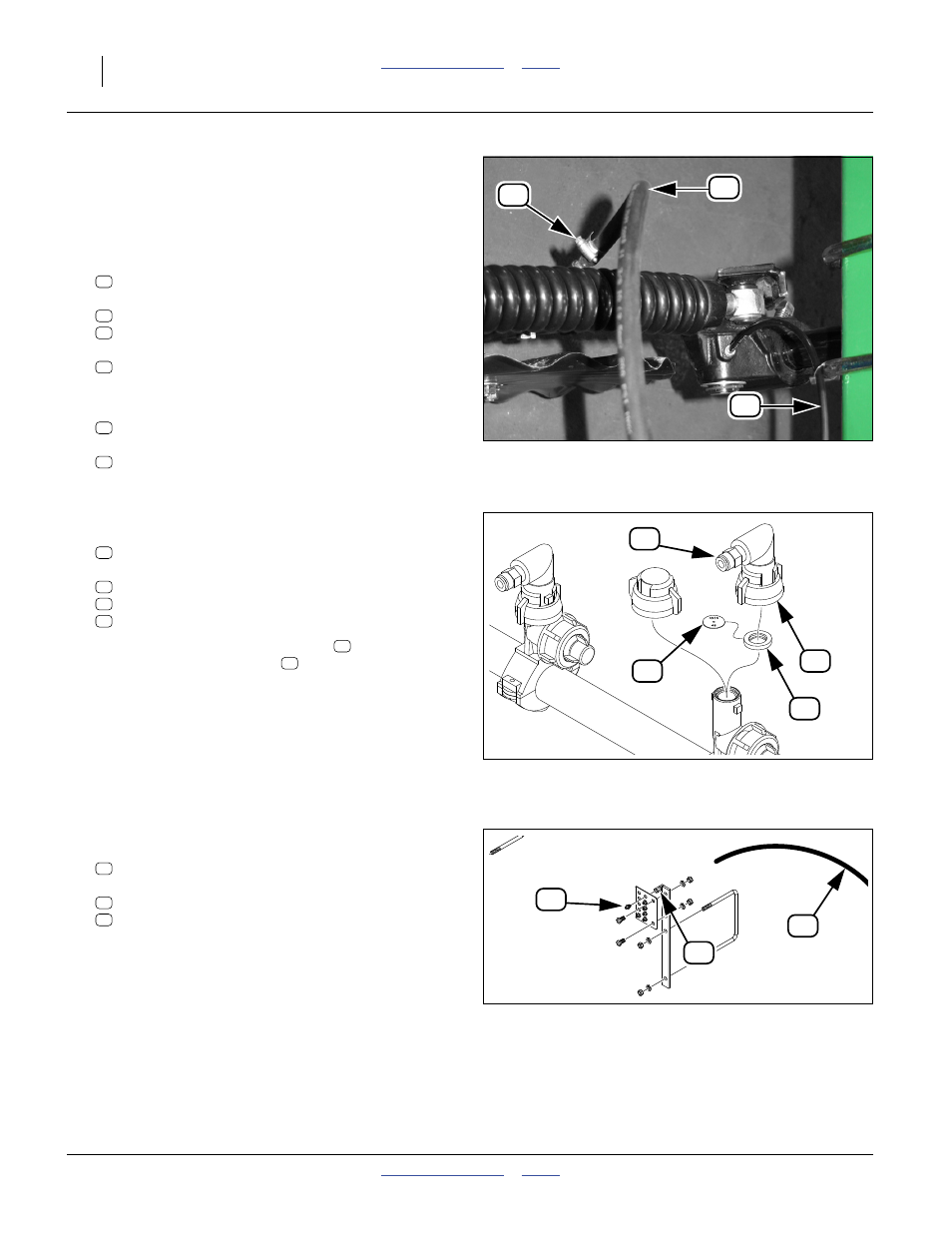
Refer to Figure 69
20. Remove and save one rear boom drop line:
990-080R HOSE 3/8 ID 150PSI EPDM
two each:
800-390C CLAMP WRM DRV #6 SS (.38-.87)
Refer to Figure 70
21. Remove and save one nozzle set:
407-373S NOZZLE ASSEMBLY - 3/8 HOSE
which includes:
830-071C AD 1/4MNPT X 3/8HB POLYPROP
832-051C NOZZLE CAP QUICK X 90X1/4 FNPT
CP18999-EPR ORIFICE SEAT STYLE GASKET
22. Remove and save the orifice plate
inside the
existing rear nozzle gasket
. The plate may or may
not be the size you need for the front side dress row.
Refer to Figure 71 and Figure 69
23. Remove and save the one rear grease bank line:
990-109R TUBE NYLON 1/4OD X 062WL
and its fittings at the grease bank:
800-130C GREASE ZERK STRAIGHT 1/8-27NPT
800-158C FTG TUBE,CONNECTOR 1/8 FNPT
Figure 69
Drop Line and Grease Connections
32028
84
83
65
51
75
71
77
83
65
Figure 70
Fertilizer Nozzle Parts
29984
82
85
80
38
59
80
82
85
38
85
Figure 71
Grease Bank Connection
31846
63
62
84
84
62
63