Disconnect side dress coulter – Great Plains NP4000 40-foot Operator Manual User Manual
Page 123
Great Plains Manufacturing, Inc.
Appendix C - Accessory Installation
119
2012-03-28
407-776M
Disconnect Side Dress Coulter
Refer to Figure 80
11. At the coulter mounted on the wing extension,
remove and save one rear boom drop line:
990-080R HOSE 3/8 ID 150PSI EPDM
two each:
800-390C CLAMP WRM DRV #6 SS (.38-.87)
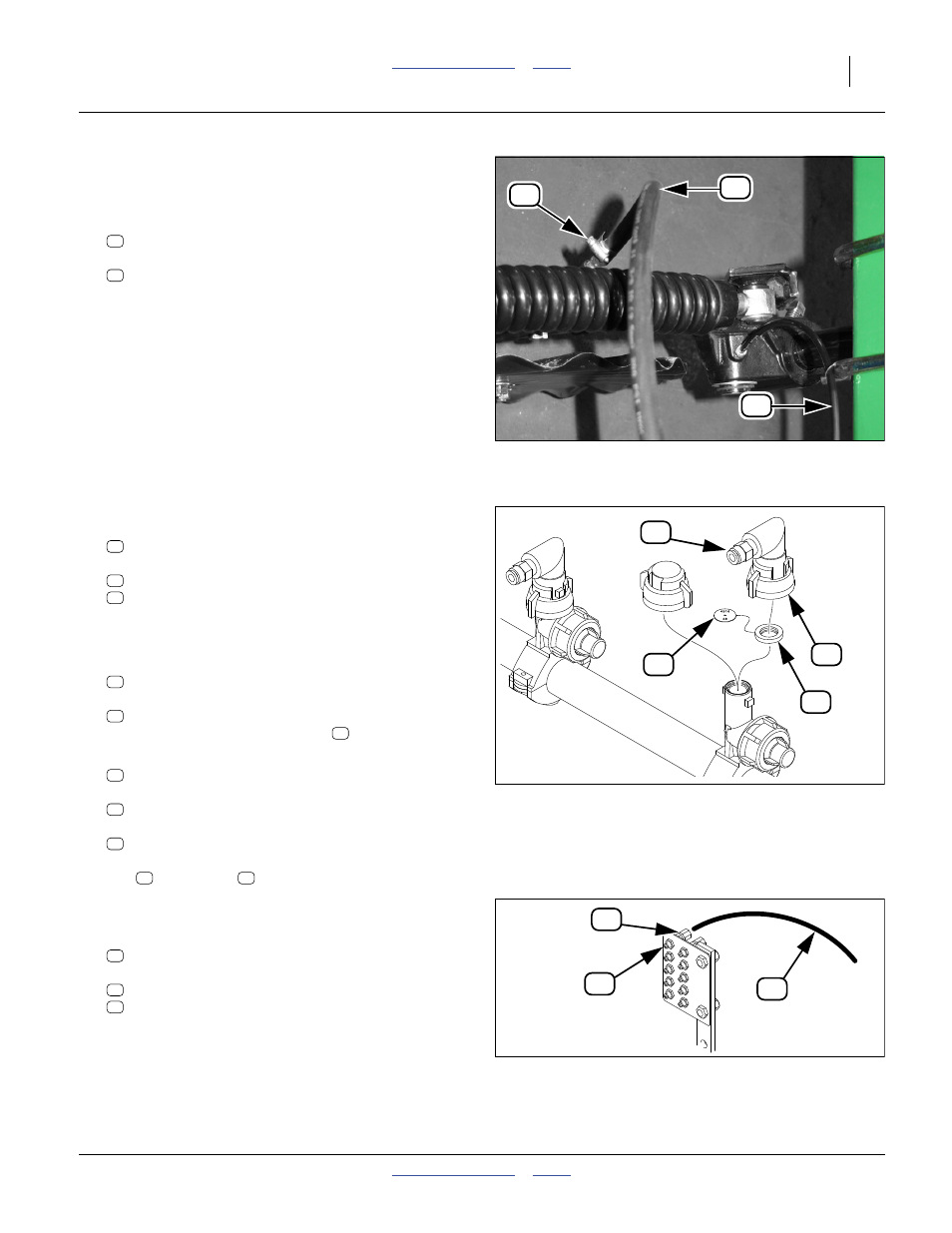
Refer to Figure 81
12. At the left end of the forward boom, remove and save
one nozzle set:
407-373S NOZZLE ASSEMBLY - 3/8 HOSE
which includes:
830-071C AD 1/4MNPT X 3/8HB POLYPROP
832-051C NOZZLE CAP QUICK X 90X1/4 FNPT
13. If this nozzle was originally removed from the rear
boom (step 14 on page 113), re-install it there.
14. Unless needed for a rear row, remove and save the:
CP18999-EPR ORIFICE SEAT STYLE GASKET
and orifice plate
832-05#C ORIFICE SPR SYS CP4916-## SS
inside the left end nozzle gasket
.
15. Select one saved:
832-042C NOZZLE SHUT OFF CAP W/ GASKET
and one saved:
CP18999-EPR ORIFICE SEAT STYLE GASKET
and if not needed elsewhere, one:
832-05#C ORIFICE SPR SYS CP4916-## SS
Seal the left end boom clamp with the shut-off
cap
and gasket
.
Refer to Figure 71 and Figure 69
16. At the coulter mounted on the wing extension,
remove and save the grease bank line:
990-109R TUBE NYLON 1/4OD X 062WL
and its fittings at the grease bank:
800-130C GREASE ZERK STRAIGHT 1/8-27NPT
800-158C FTG TUBE,CONNECTOR 1/8 FNPT
17. If this grease bank line was originally removed from
a rear coulter (step 14 on page 113), re-install the
fittings and tubing on the rear left wing grease bank.
Figure 80
Drop Line and Grease Connections
32028
84
83
65
83
65
Figure 81
Fertilizer Nozzle Parts
29984
82
85
80
38
59
80
82
85
38
85
36
37
38
36
37
Figure 82
Grease Bank Connection
32081
63
62
84
84
62
63