Connect coulter tubing – Great Plains NP4000 40-foot Operator Manual User Manual
Page 120
116
NP4000
Great Plains Manufacturing, Inc.
407-776M
2012-03-28
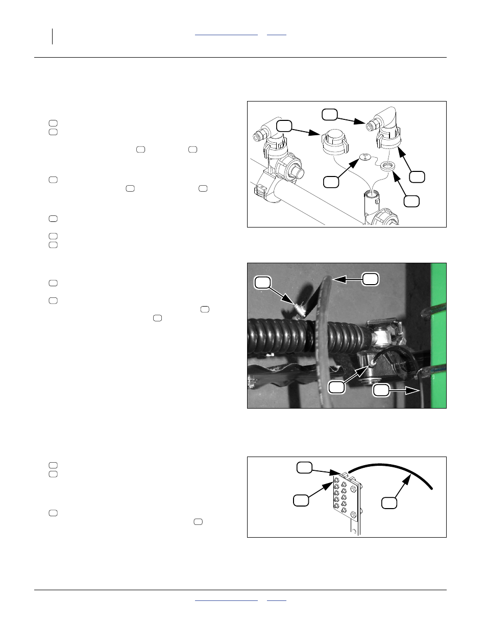
Connect Coulter Tubing
Refer to Figure 74
32. At the left end of the front boom, remove one cap
and gasket from the boom clamp:
832-042C NOZZLE SHUT OFF CAP W/ GASKET
CP18999-EPR ORIFICE SEAT STYLE GASKET
If a nozzle was removed at step 20 on page 114,
relocate the shut-off cap
and gasket
to the
open rear row boom clamp.
33. Select one new or saved:
CP18999-EPR ORIFICE SEAT STYLE GASKET
Install an orifice plate
inside the gasket
.
34. At the front left boom clamp, install one new or saved
nozzle set:
407-373S NOZZLE ASSEMBLY - 3/8 HOSE
which includes:
830-071C AD 1/4MNPT X 3/8HB POLYPROP
832-051C NOZZLE CAP QUICK X 90X1/4 FNPT
Refer to Figure 75 and Figure 74
35. Select one new or saved:
990-080R HOSE 3/8 ID 150PSI EPDM
and two:
800-390C CLAMP WRM DRV #6 SS (.38-.87)
Connect this hose from the nozzle adaptor
to the
coulter applicator attachment
.
Refer to Figure 76
36. Select one set new or saved:
800-130C GREASE ZERK STRAIGHT 1/8-27NPT
800-158C FTG TUBE,CONNECTOR 1/8 FNPT
Install these at an available hole in the front left wing
grease bank.
37. Select the new or saved:
990-109R TUBE NYLON 1/4OD X 062WL
Connect this from the grease bank fitting
to the
coulter pivot fitting (not shown). Secure with cable
ties between grease bank and coulter.
38. Pump grease until it emerges at the coulter pivot.
Figure 74
Fertilizer Nozzle Installation
29984
39
37
80
36
38
36
37
36
37
37
38
37
59
80
82
Figure 75
Drop Line, Grease Connections
32028
84
83
65
56
83
65
80
56
Figure 76
Grease Bank Fittings
32081
63
62
84
62
63
84
63