Using auxiliary hydraulic circuit, Pre-usage checklist – Great Plains YP1220 Operator Manual User Manual
Page 30
26
YP1220
Great Plains Manufacturing, Inc.
401-506M
03/14/2012
8.
Load the hopper with seed. If using a hydraulic auger
with the auxiliary hydraulic kit, refer to the instruc-
tions following.
9.
Open the slide gate.
10. Return the ladder and platform to the closed posi-
tion.
Flow Inconsistency and Stoppage Risk:
Talc lubricant is mandatory for all seeds, especially treated or
inoculated seed when using the precision meter. Do not use
talc lubricant when using the finger pickup meters. Use graph-
ite lubricant with finger pickup meters. Refer to “Seed Lubri-
cants” on page 71.
Using Auxiliary Hydraulic Circuit
The optional auxiliary hydraulic kit includes a manual
valve that diverts the marker hydraulic circuit to a pair of
quick-connect ports at the back of the seed cart.
1.
Extend or fold any marker that is raised. Return the
cab control for that circuit to “off”.
2.
Close any shut-off valve on your auger, and connect
the auger to the auxiliary quick-connect ports at the
back of the seed cart.
3.
At the auxiliary selector valve (near marker
sequence valve on left wing), move the handle from
“Marker” to “Auxiliary”.
4.
With no seed present, open the auger shutoff valve,
and operate the cab control to determine which set-
ting (“extend” or “retract”) turns the auger in the cor-
rect direction for seed lift.
5.
Load seed. Shutoff cab circuit, then auger. Return
Aux valve control handle to “Marker” position.
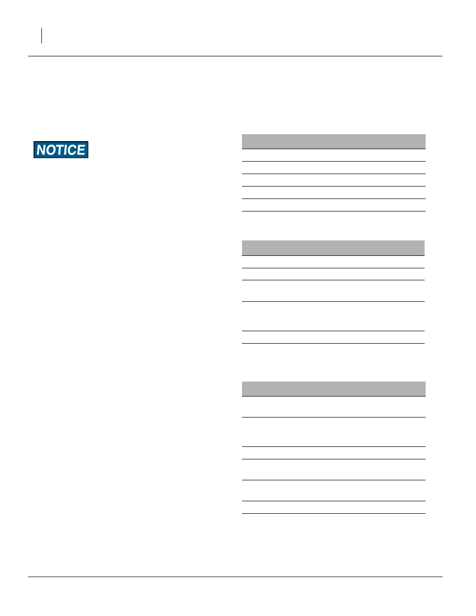
Pre-Usage Checklist
Use the following checklist as a guide to ensure the
planter is proper set before using. You may need to refer
to the assembly instructions, operator’s manual or the
Dickey-john manual to complete checklist.
MECHANICAL
❑ 1. Tongue height preset on 3-point.
❑ 2. Front to rear levelness.
❑ 3. End-to-end levelness at gauge wheels.
❑ 4. Toe in of wing frames at pull-bars.
❑ 5. Tongue hook latch operation.
❑ 6. Marker initial length.
AIR SYSTEM
❑ 7. Manifold to Pro-box or poly hopper seal.
❑ 8. Y-splitters turned on to correct rows.
❑
9.
Air leaks (small leaks from Pro-box are nor-
mal.
❑
10. Hose routings, no sags and no pinched
hoses. (Check both folded and field posi-
tions.)
❑ 11. Cleanout doors closed at meters.
❑
12. Hoses fully connected to meters and
locked.
ROW-UNITS
❑
13. Preset depth handles to 7 holes showing
above “T”
❑
14. Preset down force springs to 1st notch
(lightest) setting for most conditions, 2nd
notch otherwise.
❑ 15. Check closing wheel alignment.
❑
16. Set closing wheels to first notch (light set-
ting).
❑
17. Check meter drive coupler is engaged for
all desired rows.
❑ 18. Lock up splitter rows if needed.
❑
19. Check action and contact of side depth
wheels.