Ace pump assembly – Great Plains TSF1290 Operator Manual User Manual
Page 71
Great Plains Manufacturing, Inc.
Maintenance and Lubrication
67
05/10/2012
500-641M
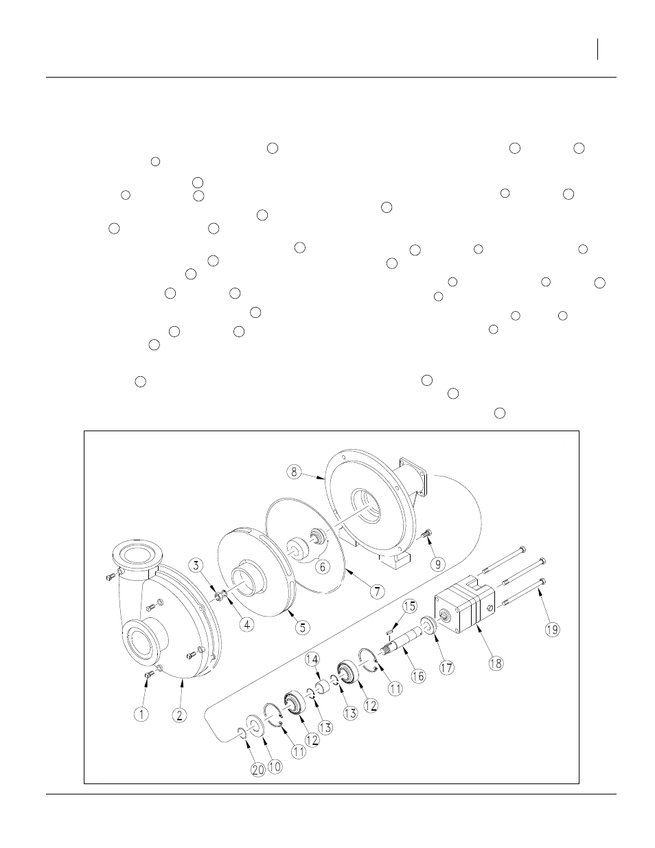
Ace Pump Assembly
Install forward internal bearing snap ring
in
mounting frame
.
2.
Press in forward bearing
from rear side of mount-
ing frame
to snap ring
.
3.
Install two external shaft retainer rings
with
spacer
between on shaft
.
4.
Press shaft assembly through forward bearing
until forward shaft snap ring
rests against inner
face of forward bearing
.
5.
Press rear bearing
over shaft
.
6.
Insert rear internal bearing snap ring
.
7.
Slide rubber slinger
over shaft
and push back
to front bearing
.
8.
Clean old sealant from mounting frame seal bore.
9.
Install o-ring
in shaft groove.
10. Apply non-hardening Type 2 Permatex or similar
under stationary seal flange.
11. Place stationary portion of seal
over shaft
and
press into seal bore cavity. Use a 1
3
⁄
8
in ID pipe or
PTO adapter to press seal flange evenly on all sides.
12. Install rotating portion of seal
over shaft
and o-
ring
by hand. The two polished seal faces should
face each other. Avoid contacting polished seal
faces.
13. Insert key
in keyway
and install impeller
on
shaft
.
14. Place lock washer
and
3
⁄
8
in lock nut
on shaft
and tighten nut
.
15. Replace volute o-ring or gasket
, volute
, and
four
3
⁄
8
in x
3
⁄
4
in cap screws
.
16. Position coupler in pump shaft slot and fill cavity sur-
rounding coupler with grease.
17. Install motor
by aligning motor tang and coupler
slot. Rotate motor
until nameplate faces up.
18. Install four
5
⁄
16
in cap screws
.
Figure 59
Ace Hydraulic Pump
23373
11
8
12
8
11
13
14
16
12
13
12
12
16
11
10
16
12
20
17
16
6
16
20
15
5
5
16
4
3
16
3
7
2
9
18
18
19