Pump maintenance & repair – Great Plains TSF1290 Operator Manual User Manual
Page 69
Great Plains Manufacturing, Inc.
Maintenance and Lubrication
65
05/10/2012
500-641M
Pump Maintenance & Repair
The Great Plains pump is designed for long life and ser-
vice. Through the years there may be a need to replace
the mechanical seal or service some component of the
pump. A mechanical seal may weep slightly, but if it
starts to drip the pump will have to be disassembled.
Before disassembling the pump be sure to wash it out
with fresh water. Refer to the parts manual for the com-
ponents of the pump.
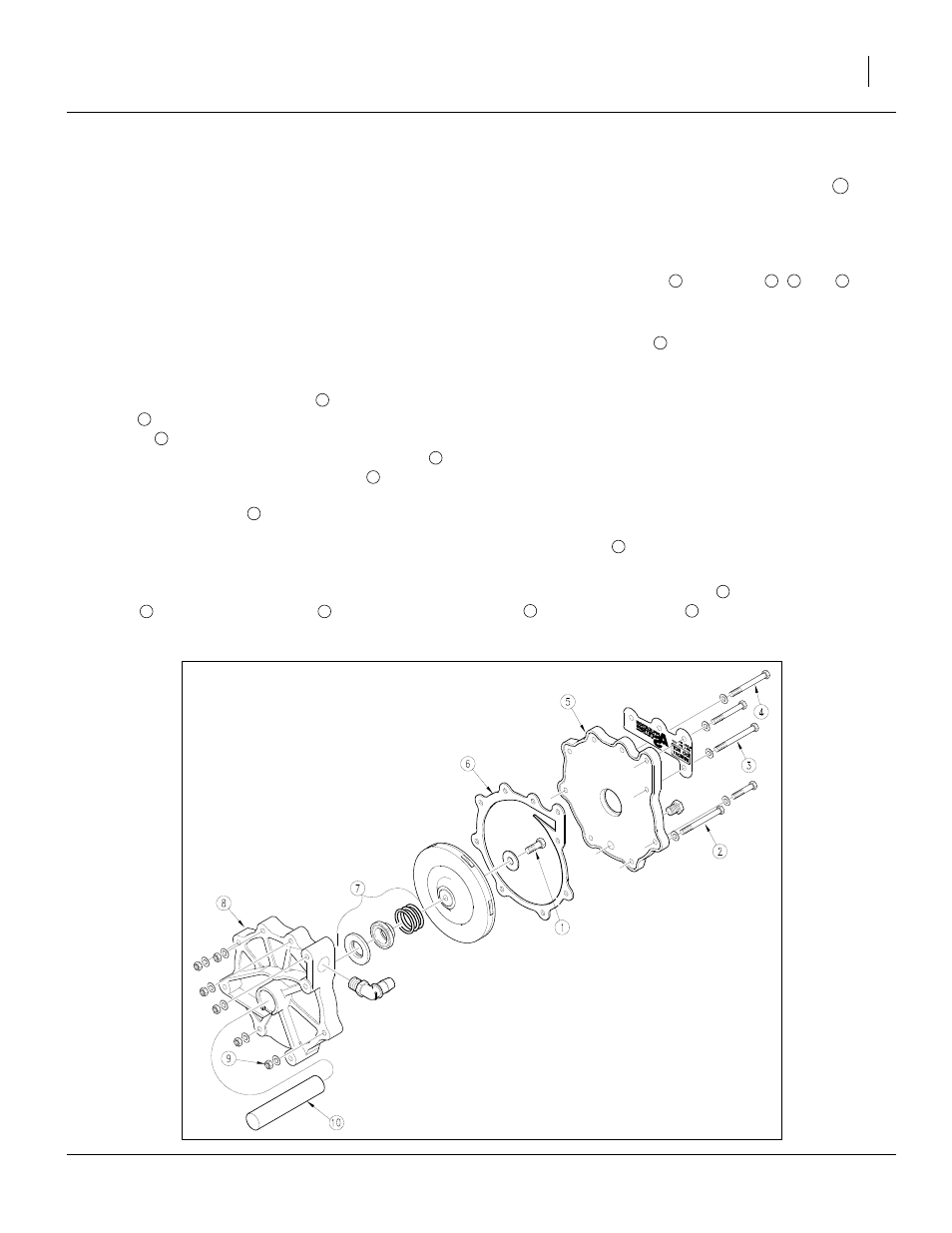
Refer to Figure 57
If the pump is leaking, before removing it from the
sprayer, run the pump with adequate water in the tank to
diagnose the actual pump problem. If fluid leaks out
between the front suction housing
and the rear volute
housing
, the housing gasket may be dried out. Give
the gasket
adequate time to absorb moisture and
swell up. If necessary, retighten the volute housing
by
alternating on opposite sides until all nuts
are torqued
to 16 - 18 ft.-lbs. It is a good practice to apply grease to
both sides of the gasket
to prevent shrinkage.
If seal replacement is required:
1.
Disassemble pump and clean all components.
2.
Assemble the ceramic ring seat of the mechanical
seal
into the volute housing
of the pump. Make
sure the ceramic seat is positioned square into the
volute housing.
3.
Clean off any grease or dirt from pump shaft
and
dry the shaft so the rubber bellows on the mechani-
cal seal will adhere to the shaft properly when
assembled.
4.
Bolt up the pump input bearing housing (not shown)
to the volute housing
using bolts
,
and
with
spacers (not furnished) for alignment and assembly
of the shaft seal.
5.
Assemble the seal
without its spring, on the pump
shaft by pushing on the inside rubber portion of the
seal using water as the lubrication. The graphite seal
face should touch the white ceramic seat face. The
rubber bellows adhering to the pump shaft should
not protrude more than
1
⁄
16
in (1.6mm) beyond the
stainless steel ring located on the impeller side of the
seal.
6.
Assemble the seal’s spring and the impeller, being
careful not to move the mechanical seal that has
been positioned on the pump shaft. Torque the
impeller bolt
16-18 ft-lbs (22-24 N-m).
7.
Remove the three bolts and spacers. Using gun
grease, lubricate the gasket
. Assemble the gasket
and suction housing
using bolts, flat washers
and locknuts. Torque nuts 16 - 18 ft./lbs.
Figure 57
Centrifugal Pump Assembly
11591
5
8
6
8
9
6
7
8
10
8
2
3
4
7
1
6
6
5