Hitch shims, Height switch adjustment, Hitch shims height switch adjustment – Great Plains 3PYPA Operator Manual User Manual
Page 62
58
3PYPA
Great Plains Manufacturing, Inc.
401-647M
03/20/2012
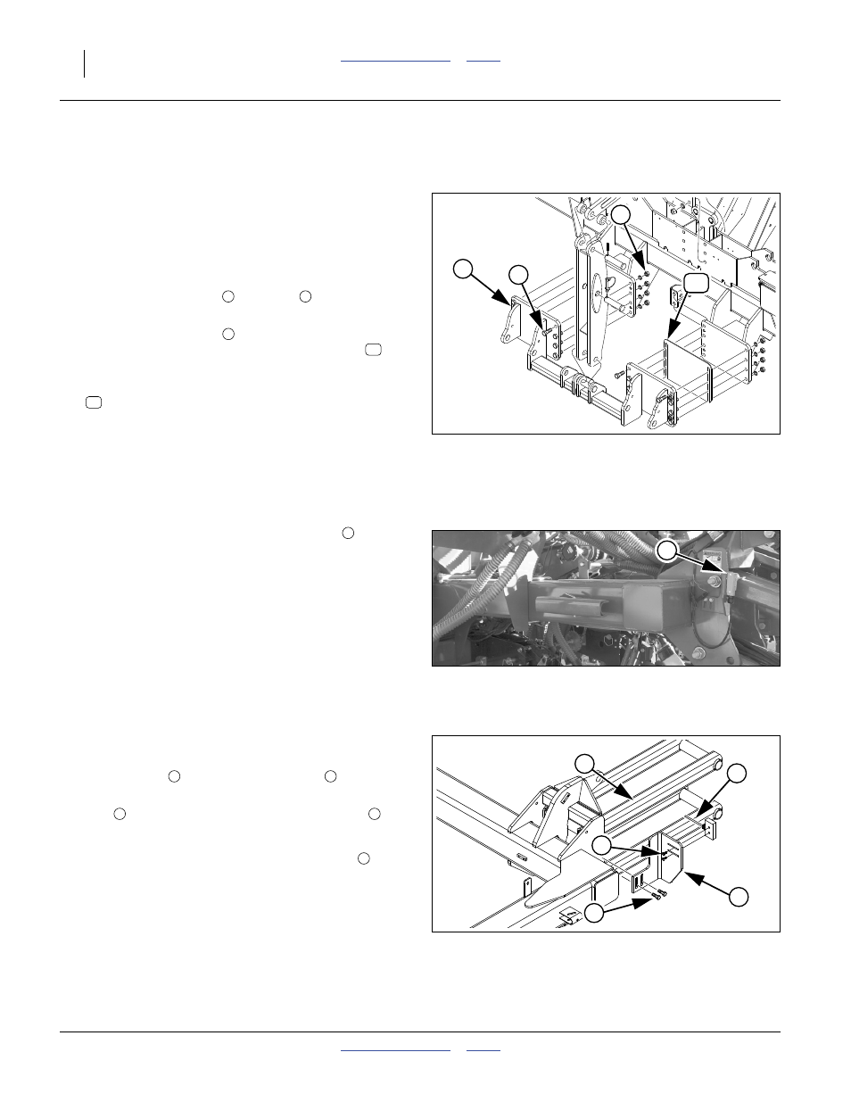
Hitch Shims
Refer to Figure 65
(an exploded view - remove only specified parts)
If the planter tends to pull to the right or left, inserting,
moving or stacking hitch shims may correct the problem.
The standard planter has one shim installed on the left. A
spare hitch shim was shipped with the planter.
To remove or insert a shim:
1.
Loosen the eight nuts
and bolts
on the lower
hitch, only on the side to be changed.
2.
At the four set screws
, loosen the four jam nuts.
Drive the set screws in until the existing shim
is
free, or the gap is large enough to insert a shim.
3.
From the top, insert or remove:
401-943D SHIM HITCH FLANGE
4.
Back out the four set screws. Tighten the eight nuts
and bolts. Turn the set screws in until they make con-
tact. Secure them with the four jam nuts.
Height Switch Adjustment
Refer to Figure 66
The 3PYPA planter includes a sensing switch
that sig-
nals the seed monitor (and activates the optional hydrau-
lic drive), when the planter is lowered for planting.
Although factory-preset for typical planting conditions,
Great Plains recommends adjusting this switch for your
exact field conditions and planting depth. Check the
switch seasonally thereafter, or when planting conditions
change. Also perform this adjustment if the switch is
replaced or dislodged.
The switch is located on the parallel arms connecting the
planter mainframe to the air cart.
Refer to Figure 67
1.
Lower the planter to the height at which seed deliv-
ery is to begin.
2.
Loosen bolts
holding switch bracket
to frame.
3.
Move bracket and switch up or down so switch toggle
arm
makes contact with upper parallel arm
.
4.
Move switch/bracket down
1
⁄
4
in. Tighten bolts.
Note: It may be necessary to loosen the screws
hold-
ing the switch to the bracket and rotate the switch
slightly on the bracket.
Note: If the switch is ever completely removed, be sure to
replace it with the cable exit at the bottom. If the ca-
ble is at the top, switch operation is reversed, and
moisture will accumulate in the switch, causing
eventual switch failure.
Null4:
Figure 65
Hitch Shim
29859
1
15
2
3
1
2
3
15
15
Null4:
Figure 66
Height Switch Location
29123
1
1
Null4:
Figure 67
Height Switch Adjustments
25442
5
4
3
2
6
2
3
4
5
6