Initial marker setup (option), Marker speed adjustment – Great Plains 3PYPA Operator Manual User Manual
Page 167
Great Plains Manufacturing, Inc.
Appendix B - Initial and Option Setup
163
03/20/2012
401-647M
• Wing Flex Lock pin must be installed. Wing (down)
lock pin must be removed and wing flex lock pins must
be removed and in storage (Refer to Figure 33 on
page 34).
Refer to Figure 160 and Figure 161 (which depict the planter
on pavement - perform this adjustment in the field)
1.
Measure from the bottom of the wing tool bar to the
ground at the outer end of each wing.
2.
Compare to the measurement at the outer end of the
center tool bar, at the wing pivot location. All mea-
surements should be identical, and nominally 26 in.
3.
If measurements do not match, loosen upper wing
link arm lock nut
, and adjust link length.
4.
If adjustments are needed on either side, re-check
the other side after each adjustment, and re-adjust it
as needed.
5.
Once level, tighten the wing link arm lock nut
.
Initial Marker Setup (Option)
Marker Speed Adjustment
You may be injured if hit by a folding or unfolding marker.
Markers may fall quickly and unexpectedly if the hydraulics
fail. Never allow anyone near the planter when folding or
unfolding the markers.
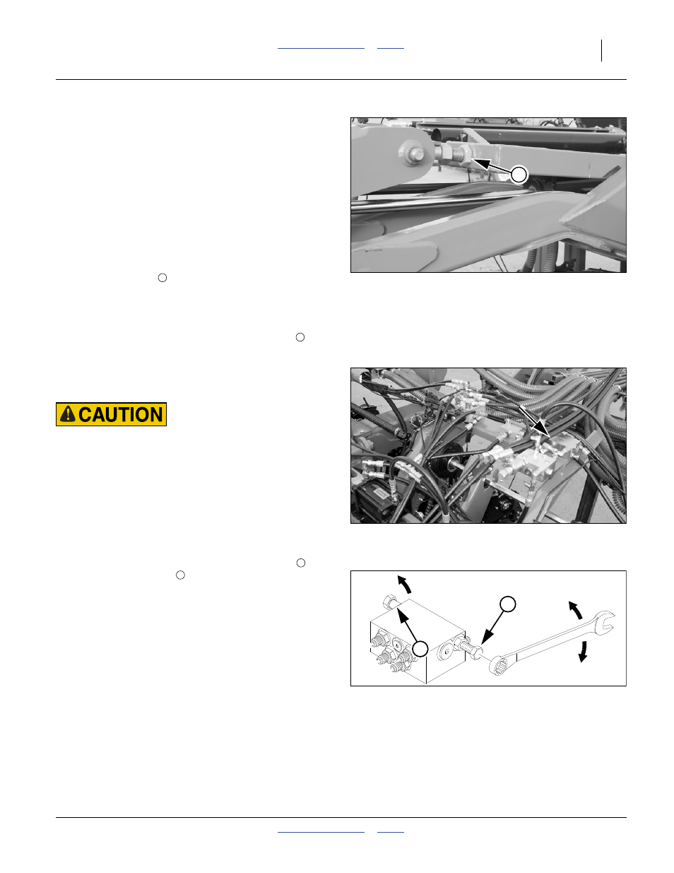
Refer to Figure 162 and Figure 163
Adjust folding speed for dual markers with hex adjust-
ment screws on the sequence valve body. The valve
sequence body is top left center section, near front.
Loosen jam nuts before making adjustments.
There is one adjustment screw for fold-out speed
and
one for fold-down speed
. You can identify adjustment
screws by markings stamped in valve body.
Turn adjustment screws clockwise (S: slower) to
decrease folding speed and counterclockwise (F: faster)
to increase folding speed.
With tractor idling at a normal operating speed, adjust
marker folding to a safe speed. Excessive folding speed
could damage markers and void the warranty.
After adjusting the folding speed, tighten jam nuts on hex
adjustment screws to hold settings.
Null4:
Null4:
Figure 161
Leveling Wing with Arm Link
25438
1
1
1
Null4:
Figure 162
Marker Sequence Valve Location
25440
Null4:
Figure 163
Marker Extension Adjustment
14048
F
S
S
1
2