Steering maintenance, Steering system hydraulic bleeding, Steering system modes of operation – Great Plains 3PYPA Operator Manual User Manual
Page 111: Steering calibration
Great Plains Manufacturing, Inc.
Maintenance and Lubrication
107
03/20/2012
401-647M
Steering Maintenance
Steering System Hydraulic Bleeding
The steering system is self-purging and never requires
bleeding if operated with all four hoses correctly con-
nected.
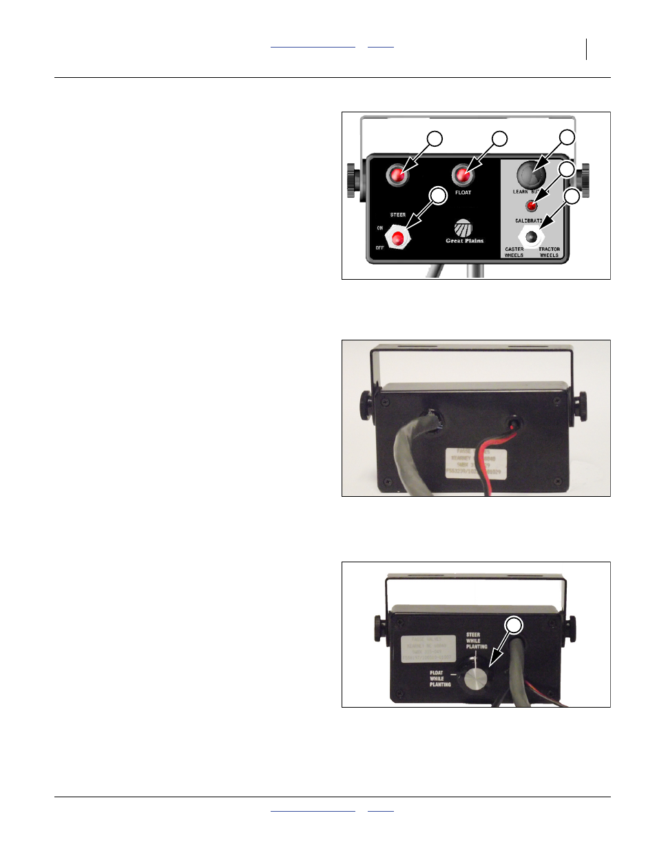
Steering System Modes of Operation
(APPLIES ONLY TO PLANTERS s/n B1027J+)
Refer to Figure 133
There are two modes of operation for the steering sys-
tem on the 3PYP and 3PYPA planters. Which mode of
operaton to use is based on whether the tractor is manu-
ally steered or has an auto-steer system.
If the tractor is manually steered then the planter steering
system should be set to “Steer While Planting” mode. In
this mode the planter steering system is always active.
If the tractor is steered with an auto-steer system then
the planter steering system should be set to the “Float
While Planting” mode. In this mode the steering system
is active only when the planter is in the raised position.
When the planter is in the down (planting position) the
planter steering system is in the float mode.
Steering Calibration
Hydraulic-powered planter hydraulic steering is standard
on the 3PYPA planter.
The hydraulic steering system has two calibration
modes:
a.
one for caster wheel sensor calibration
b.
one for tractor wheel sensor calibration.
After initial wheel calibration at delivery of the planter,
periodic re-calibration is necessary in the following cir-
cumstances:
• Re-calibrate for use with a different tractor.
• Re-calibrate if maintenance required dismounting any
steering sensor, tire size or tractor tire size and/or
wheel arrangement has changed.
• Great Plains recommends seasonal re-calibration.
• Re-calibrate if steering software is updated.
Null4:
Figure 131: Calibration
Steering Control Module Front View
29850
3
2
1
4
6
5
Null4:
Figure 132
s/n B1026J- Module Rear View
31775
Null4:
Figure 133
s/n B1027J+ Module Rear View
31698
7