ClearOne PAN6400 User Manual
Page 18
NetStreams Panorama System Installation Guide
2-8
All specifications subject to change without notification. All rights reserved. Copyright © 2006 NetStreams
Main +1 512.977-9393 / fax +1 512.977.9398 / Toll Free Technical Support +1 866-353-3496
3600 W. Parmer Lane, Suite 100; Austin, TX 7872
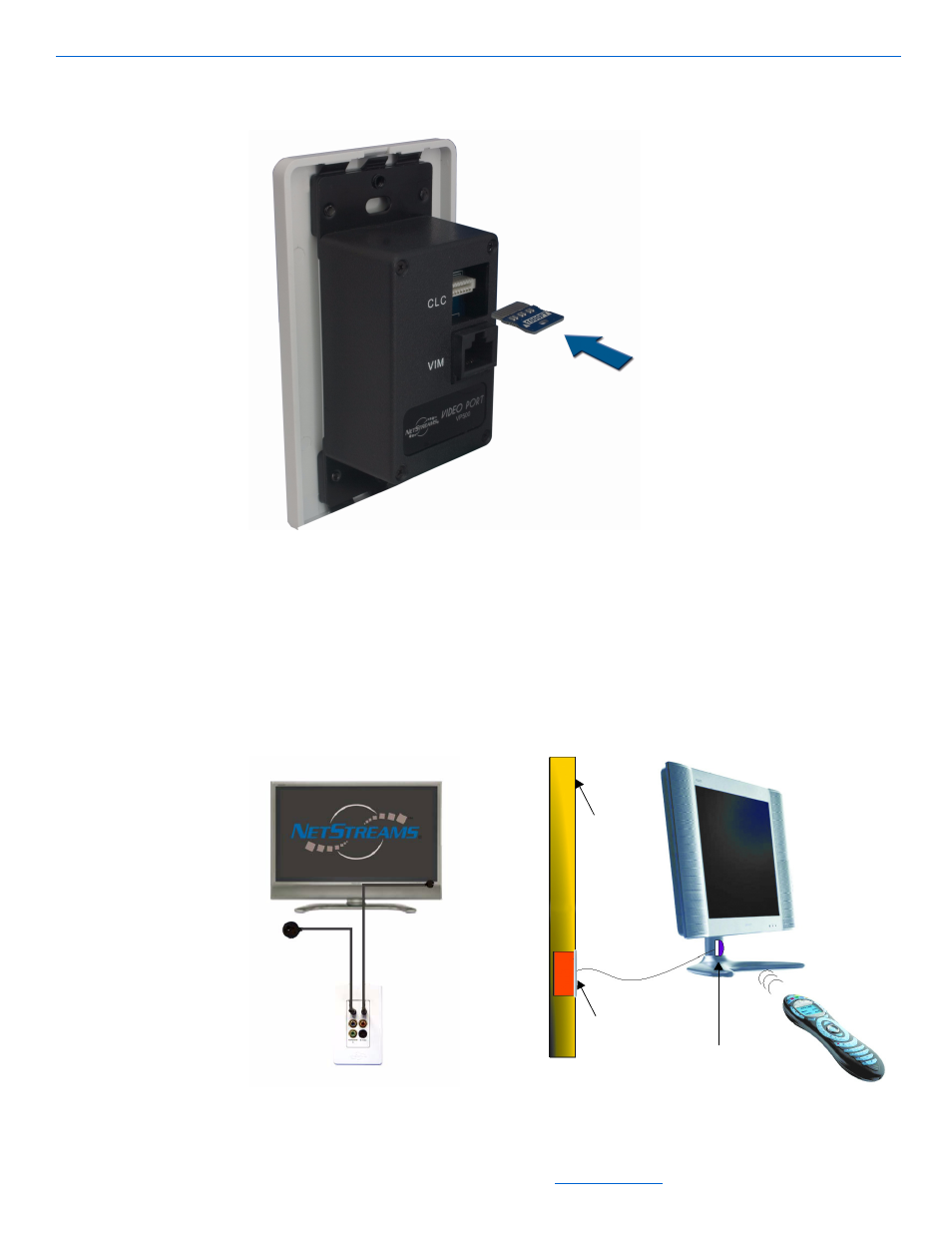
Figure 2-6 shows an example of how to insert a chip into the Panorama Video Port.
Figure 2-6
CLC chip (insertion)
Figure 2-7 shows the IR connection to and from the Video Ports. Connect the IR
Receiver to the Video Port and place it in a location where it can receive the IR signal
from the source remote. The best location is shaded from fluorescent light with the
dome facing the IR remote.
Place the IR Emitter over the IR window on the front of the display and connect it to
the Video Port.
Figure 2-7
Connecting PAN6400 VDC IR Receiver and Emitter
IR
Emitter
IR Receiver
PANVP700
IR Emitter
PANVP700
Wall