Page 3 – SARGENT 7000 Series Vertical Rod Lock User Manual
Page 3
PAGE 3
7860D
4/13
Copyright ©2007, 2013 Sargent Manufacturing Company, an ASSA ABLOY Group company. All rights reserved.
Reproduction in whole or in part without the express written permission of Sargent Manufacturing Company is prohibited.
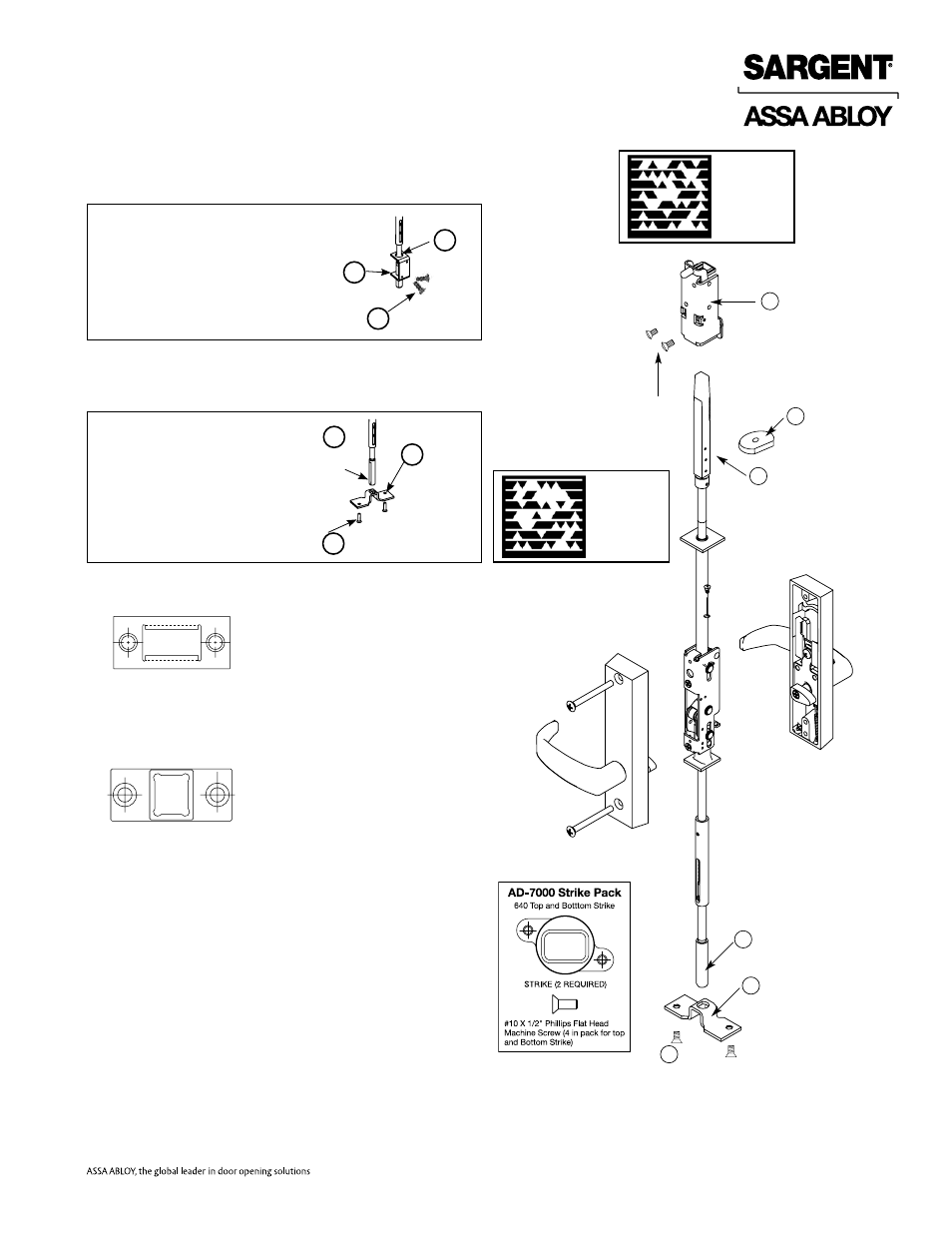
8) Slide rod silencer (G) over top bolt (F) onto rod.
NOTE:
The teeth on the rod should face the teeth on the top case.
9) SLIDE TOP case (E) over top bolt (F). Secure with (2) screws (HH).
10A)
For AD-7000 bottom bolt
: Install bottom plate (M) over bottom bolt
(L) and secure with (2) screws (HH) using holes (6A).
10B)
For MD-7000 & 12-MD-7000:
Install bottom plate (M) over bottom
bolt (L) and secure with (2) screws (DD) using tapped holes (7A).
11) Install door into the frame using hinges.
12) 650 Top Strike
ATTACH 650 Top Strike to door frame, (2) #10-24 x 1/2"
flat head screws (Reference template 4449).
13) 606 Bottom Strike
Attach 606 Bottom Strike to floor under bottom bolt,
(2) 1/4 - 20 x 2 Phillips head machine screws and
(2) anchor nuts (Reference template 4449).
650 Top Strike
606 Bottom strike
Machine screw and anchor
(2 pieces)
Top case
HH Screws (2)
DD Screws (2)
Silencer
G
E
Top bolt
F
Bottom bolt
L
Bottom plate
M
For AD-7000 Bottom Bolt
Install bottom plate (M) over the
bottom bolt (L) and secure with two
#10-24 x 3/8" oval head screws (DD)
using holes (6A)
#10-24 x 3/8" Oval Head Screws
For MD-7000 & 12-MD-7000
Bottom Bolt
Install bottom plate (M) over
the bottom bolt (L) and secure
with two 1/4-20 x 1/2" flat head
screws (DD) using tapped
holes (7A)
1/4-20 x 1/2" flat
head screw
M
DD
Bottom
bolt
L
Bottom
Plate
14) BEFORE CLOSING DOOR
Adjust bolts per steps 6 & 7 as needed:
a) Either lever retracts both bolts.
b) Bolts stay retracted (hold back).
c) Bolts release when door closes; button inside top
of door hits frame.
d) Bolts engage strikes, 1/4"- 5/16".
Bottom
bolt
Bottom
Plate
M
HH
L
Scan to see a
video of this
installation step.
Scan to see a
video of this
installation step.