Page 2 – SARGENT 7000 Series Vertical Rod Lock User Manual
Page 2
Spindle cam
Copyright ©2007, 2013 Sargent Manufacturing Company, an ASSA ABLOY Group company. All rights reserved.
Reproduction in whole or in part without the express written permission of Sargent Manufacturing Company is prohibited.
PAGE 2
7860D
4/13
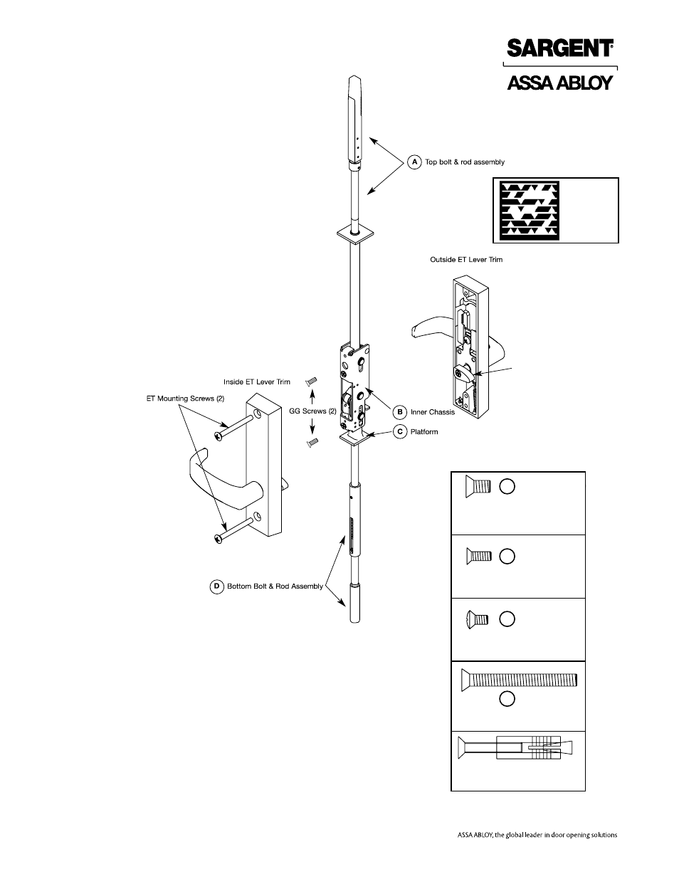
2) Screw top bolt & rod assembly (A) and bottom bolt & rod
assembly (D) into inner chassis (B).
3) Slide complete assembly into top of door.
4) Attach inner chassis (B) to door with (2) screws (GG).
5) Attach inside and outside ET Lever trims using ET
mounting screws. Insert spindle thru 1-1/4" thru hole.
Spindle cams must be UNDER inner chassis platform (C).
6) Adjust TOP BOLT AND ROD assembly (A) with the inside
lever rotated in a down position.
For 1/8" GAP OR LESS between top of door and door
frame, rotate bolt even with top of door.
For 1/8" GAP OR GREATER between top of door and
door frame, rotate bolt to gap minus 1/8" above door.
7) Adjust BOTTOM BOLT AND ROD assembly (D) with the
inside lever rotated in a down position.
For 1/8" GAP OR LESS between door bottom and high
point of floor, rotate bolt to make even with bottom of door.
For 1/8" GAP OR GREATER between door bottom and
high point of floor, rotate bolt to gap minus 1/8" below door.
Scan to see a
video of this
installation step.
Machine screw and anchor
(2 pieces)
DD
Bottom case mounting screw
(1/4"-20 x 1/2" Phillips flat head
machine screw 2 pcs) [not used with
nb prefix]
GG
HH
ET
(2) Inner chassis screws &
(2) top strike screws (# 10-24 x 1/2"
Phillips flat head machine screws, 4 pcs)
Top case mounting screw
(#10-24 x 3/8" Phillips oval head
machine screw 2 pcs)
ET Mounting Screw (1/4"-20 x 3"
Phillips oval head mach.screw 2 pcs)
Bottom strike mounting screw
(2) 1/4-20 x 2 Phillips head machine
screws and (2) anchor nuts